Bose 901 Series IV Owner's guide - Page 8
Equalizer/Processing
 |
View all Bose 901 Series IV manuals
Add to My Manuals
Save this manual to your list of manuals |
Page 8 highlights
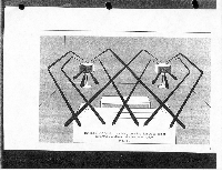
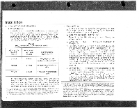
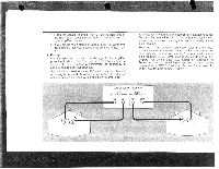
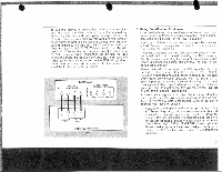
Installation C. CONNECTING THE EQUALIZER IT IS MOST IMPORTANT THAT YOU FOLLOW THESE INSTRUCTIONS FOR OPTIMUM PERFORMANCE OF YOUR 901 SERIES IV SPEAKER SYSTEM. 1. Using The Tape Monitor Circuit The connection methods described in this section can be used with virtually all integrated amplifers, preamplifiers, and receivers.t Using the tape monitor circuit has two advantages: When using conventional loudspeakers or headphones, the tape monitor circuit allows disconnection of the Active Equalizer by turning off the tape monitor switch on your control amplifier; this is important because conventional speakers and headphones should not be used with the Active Equalizer. (See SECTION IV.) Also, optimum system noise performance is obtained when connecting the equalizer in the tape monitor circuitry. When using this procedure, you should realize that the 901 equalizer is being connected to your equipment as if it were a tape recorder, using the tape monitor connections of your control amplifier. NOTE: Check your control equipment to determine if your unit has any additional switching flexibility. Some recently j introduced units now feature switching facilities called Tape Monitor 3, External Equalizer/Processing, or Noise Reduction Connections. The equalizer can be connected to these terminals allowing greater system flexibility if re- quired. fro make connection easier, we are going to refer to all of these various corn ponents as the "control amplifier." 8 Referring to FIGURE 4, connect the Active Equalizer according to the following instructions: a. Turn off all power to your high-fidelity system. b. If you have a tape recorder, disconnect it from your control amplifier. (Instructions in SECTION IV will tell you how to reconnect your tape recorder to the system after the equalizer has been installed.) c. Using one of the cables supplied with the equalizer, connect the LEFT channel OUTPUT of the equalizer to the LEFT or "A" channel of the tape monitor circuit of your control amplifier. (This terminal may also be labeled PLAYBACK or TAPE IN.) d. Connect the RIGHT channel OUTPUT of the equalizer to the RIGHT or "B" channel tape monitor connection of your control amplifier. e. Connect the LEFT channel INPUT terminal of the equalizer to the LEFT or "A" channel TAPE RECORD connection of your control amplifier. (This terminal may also be labeled TAPE OUT or REC OUT.) f. Connect the RIGHT channel INPUT connection to the RIGHT or "6" channel TAPE RECORD connection of your control amplifier. g. Plug the ac power cord of the equalizer into a "switched" ac outlet on your control amplifier so that the equalizer will automatically be turned on or off with the power switch of your equipment. If the preceding steps are unclear, it may be due to the different nomenclature used by various manufacturers of amplifying equipment. Consult your control amplifier's instruction manual and refer to the section describing the connection of a tape recorder. Remember, the equalizer is connected just like a tape recorder.
-
 1
1 -
2
-
 3
3 -
 4
4 -
 5
5 -
 6
6 -
 7
7 -
 8
8 -
 9
9 -
 10
10 -
 11
11 -
 12
12 -
 13
13 -
14
-
15
-
16
-
17
-
18
-
19
-
20
 |
 |
