Bose Cinemate Owner's guide - Page 12
Standby and Power LED indicators - interface module
 |
UPC - 017817372336
View all Bose Cinemate manuals
Add to My Manuals
Save this manual to your list of manuals |
Page 12 highlights
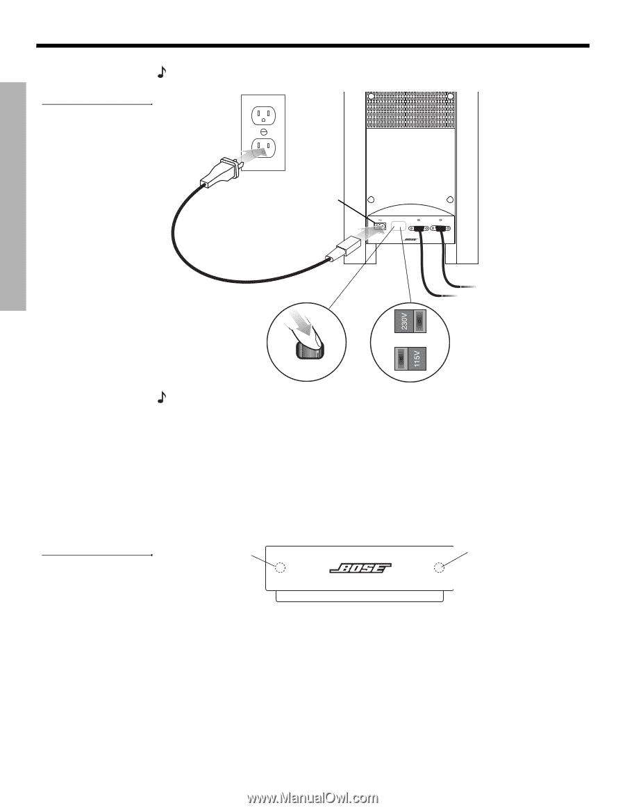
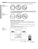
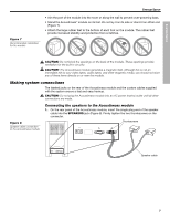
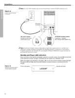
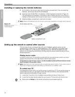
SYSTEM SETUP SYSTEM SETUP Figure 13 Power cord as the final connection Français Español English Note: On 220-240V models only, turn the Acoustimass® module POWER switch to on (l). AC power connector SPEAKERS AC power switch Provided on 220-240V rated systems only 115/230V selection switch Provided on 115/230V dual-voltage rated systems only Figure 14 Standby and power LEDs on the Interface module Note: Bose recommends using a safety agency-approved surge protector on all electronic equipment. Voltage variations and spikes can damage electronic components in any system. A quality suppressor can eliminate the vast majority of failures attributed to surges and may be purchased at electronics stores. Standby and Power LED indicators Once you have connected the CineMate™ system to a power source, the red LED on the front of the Interface module will light, indicating that the system is in Standby mode. When the system is powered on, the green LED on the front of the Interface module will light. The green LED will flash each time the Interface module receives a command from the remote. Power LED (green) Standby LED (red) 12
-
 1
1 -
2
-
3
-
4
-
5
-
6
-
 7
7 -
 8
8 -
 9
9 -
 10
10 -
 11
11 -
 12
12 -
 13
13 -
 14
14 -
 15
15 -
 16
16 -
 17
17 -
18
-
19
-
20
-
21
-
22
-
23
-
24
 |
 |