Bose Model 301 Owner's guide - Page 8
coloration
 |
View all Bose Model 301 manuals
Add to My Manuals
Save this manual to your list of manuals |
Page 8 highlights
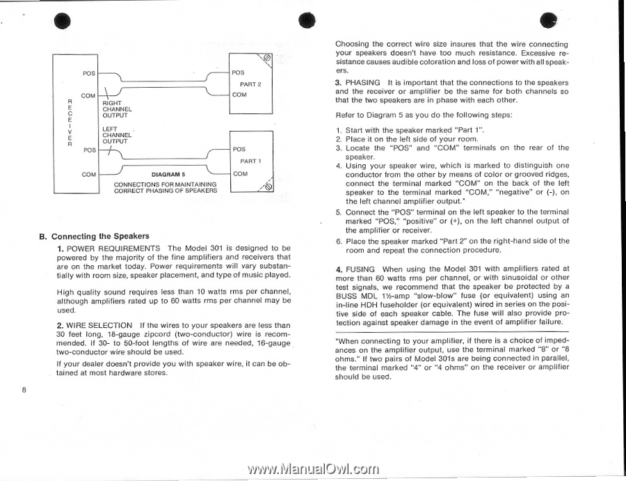
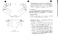
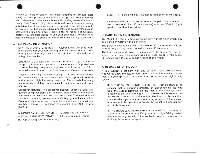
• • POS COM \ J R RIGHT E CHANNEL C OUTPUT E LEFT E R CHANNEL OUTPUT POS COM DIAGRAM 5 CONNECTIONS FOR MAINTAINING CORRECT PHASING OF SPEAKERS POS PART 2 COM POS PART 1 COM B. Connecting the Speakers 1. POWER REQUIREMENTS The Model 301 is designed to be powered by the majority of the fine amplifiers and receivers that are on the market today. Power requirements will vary substantially with room size, speaker placement, and type of music played. High quality sound requires less than 10 watts rms per channel, although amplifiers rated up to 60 watts rms per channel may be used. 2. WIRE SELECTION If the wires to your speakers are less than 30 feet long, 18-gauge zipcord (two-conductor) wire is recommended. If 30- to 50-foot lengths of wire are needed, 16-gauge two-conductor wire should be used. If your dealer doesn't provide you with speaker wire, it can be obtained at most hardware stores. 8 • Choosing the correct wire size insures that the wire connecting your speakers doesn't have too much resistance. Excessive resistance causes audible coloration and loss of power with all speakers. 3. PHASING It is important that the connections to the speakers and the receiver or amplifier be the same for both channels so that the two speakers are in phase with each other. Refer to Diagram 5 as you do the following steps: 1. Start with the speaker marked "Part 1". 2. Place it on the left side of your room. 3. Locate the "POS" and "COM" terminals on the rear of the speaker. 4. Using your speaker wire, which is marked to distinguish one conductor from the other by means of color or grooved ridges, connect the terminal marked "COM" on the back of the left speaker to the terminal marked "COM," "negative" or (-), on the left channel amplifier output.' 5. Connect the "POS" terminal on the left speaker to the terminal marked "POS," "positive" or (+), on the left channel output of the amplifier or receiver. 6. Place the speaker marked "Part 2" on the right-hand side of the room and repeat the connection procedure. 4. FUSING When using the Model 301 with amplifiers rated at more than 60 watts rms per channel, or with sinusoidal or other test signals, we recommend that the speaker be protected by a BUSS MDL 112/ -amp "slow-blow" fuse (or equivalent) using an in-line HDH fuseholder (or equivalent) wired in series on the positive side of each speaker cable. The fuse will also provide protection against speaker damage in the event of amplifier failure. 'When connecting to your amplifier, if there is a choice of impedances on the amplifier output, use the terminal marked "8" or "8 ohms." If two pairs of Model 301s are being connected in parallel, the terminal marked "4" or "4 ohms" on the receiver or amplifier should be used.
-
 1
1 -
2
-
 3
3 -
 4
4 -
 5
5 -
 6
6 -
 7
7 -
 8
8 -
 9
9 -
 10
10 -
 11
11 -
 12
12
 |
 |