Bowflex Revolution Accessory Rack Assembly Manual - Page 6
Bowflex Revolution Accessory Rack Manual
 |
View all Bowflex Revolution Accessory Rack manuals
Add to My Manuals
Save this manual to your list of manuals |
Page 6 highlights
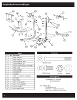
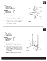
step Parts: 3 • Base assembly from Step 2 • Base Support (#1) � � �� Hardware Qty • 2 3/4" Bolts (#14) 2 • Washers (#16) 4 • Nuts (#15) 2 Tools: • Allen wrench (7/32") �� • Wrench/Socket (9/16") or Open End Wrench 3-1 Carefully tilt the base assembly forward to rest on the four Tube ends. 3-2 Attach the Base Support (#1) to the Base Bracket Figure 3 (#2) using the hardware shown in Figure 3. Make sure that the Base Support feet are pointing away from the base assembly. Note: Do not tighten hardware at this time. 3-3 Turn the base assembly upright to rest on all four feet. step Parts: • Base Plate assembly from Step 1 4 • Base assembly from Step 3 Hardware Qty • 2 3/4" Bolts (#14) 4 • Washers (#16) 8 • Nuts (#15) 4 � Tools: • Allen wrench (7/32") • Wrench/Socket (9/16") or Open End Wrench �� 4-1 Place the Base Plate (#6) on the lower Left Tube (#11) and Right Tube (#12), narrow edge toward the Tube uprights and the curved edges outside the Tubes. Align the bolt holes in the Base Plate and Tubes. Install the hardware in the two bolt holes closer to the uprights. See Figure 4. Figure 4 4-2 At the two bolt holes farther from the Tube uprights, insert a 2 3/4" Bolt (#14) through a Washer (#16) and into each bolt hole. 4-3 Carefully tilt the base assembly forward to rest on the four Tube ends. Install a Washer (#16) and Nut (#15) onto each of the Bolts from Step 4-2. Note: Do not tighten hardware at this time. 4-4 Turn the base assembly upright to rest on all four feet. 6
-
 1
1 -
 2
2 -
 3
3 -
 4
4 -
 5
5 -
 6
6 -
 7
7 -
 8
8 -
 9
9 -
 10
10 -
 11
11 -
 12
12
 |
 |
