Brother International 1800C Service Manual - Page 70
respectively
 |
UPC - 012502603764
View all Brother International 1800C manuals
Add to My Manuals
Save this manual to your list of manuals |
Page 70 highlights
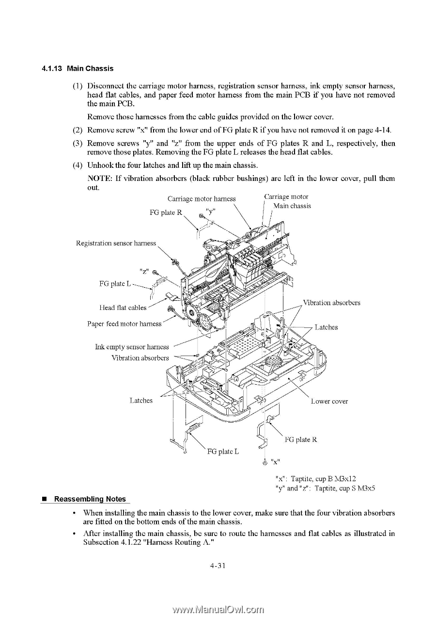
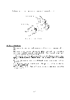
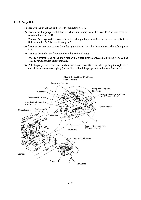
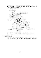
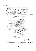
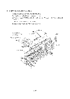
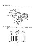
4.1.13 Main Chassis (1) Disconnect the carriage motor harness, registration sensor harness, ink empty sensor harness, head flat cables, and paper feed motor harness from the main PCB if you have not removed the main PCB. Remove those harnesses from the cable guides provided on the lower cover. (2) Remove screw "x" from the lower end of FG plate R if you have not removed it on page 4-14. (3) Remove screws "y" and "z" from the upper ends of FG plates R and L, respectively, then remove those plates. Removing the FG plate L releases the head flat cables. (4) Unhook the four latches and lift up the main chassis. NOTE: If vibration absorbers (black rubber bushings) are left in the lower cover, pull them out. Carriage motor harness FG plate R at,"Y" Carriage motor Main chassis „ Registration sensor harness FG plate L Head flat cables Paper feed motor harness 11, .c.-....,r,... ...,- c4~1j, ' ... tr'„pI-0P,.7,eO-1.:-„-,\.0 1'.'.f4. Abi I IL Vibration absorbers Latches Ink empty sensor harness Vibration absorbers \)(' Latches Lower cover FG plate L FG plate R " x " • Reassembling Notes "x" : Taptite, cup B M3x12 "y" and "z" : Taptite, cup S M3x5 • When installing the main chassis to the lower cover, make sure that the four vibration absorbers are fitted on the bottom ends of the main chassis. • After installing the main chassis, be sure to route the harnesses and flat cables as illustrated in Subsection 4.1.22 "Harness Routing A." 4-31
-
 1
1 -
2
-
3
-
4
-
5
-
6
-
7
-
8
-
9
-
10
-
11
-
12
-
13
-
14
-
15
-
16
-
17
-
18
-
19
-
20
-
21
-
22
-
23
-
24
-
25
-
26
-
27
-
28
-
29
-
30
-
31
-
32
-
33
-
34
-
35
-
36
-
37
-
38
-
39
-
40
-
41
-
42
-
43
-
44
-
45
-
46
-
47
-
48
-
49
-
50
-
51
-
52
-
53
-
54
-
55
-
56
-
57
-
58
-
59
-
60
-
61
-
62
-
63
-
64
-
 65
65 -
 66
66 -
 67
67 -
 68
68 -
 69
69 -
 70
70 -
 71
71 -
 72
72 -
 73
73 -
 74
74 -
 75
75 -
76
-
77
-
78
-
79
-
80
-
81
-
82
-
83
-
84
-
85
-
86
-
87
-
88
-
89
-
90
-
91
-
92
-
93
-
94
-
95
-
96
-
97
-
98
-
99
-
100
-
101
-
102
-
103
-
104
-
105
-
106
-
107
-
108
-
109
-
110
-
111
-
112
-
113
-
114
-
115
-
116
-
117
-
118
-
119
-
120
-
121
-
122
-
123
-
124
-
125
-
126
-
127
-
128
-
129
-
130
-
131
-
132
-
133
-
134
-
135
-
136
-
137
-
138
-
139
-
140
-
141
-
142
-
143
-
144
-
145
-
146
-
147
-
148
-
149
-
150
-
151
-
152
-
153
-
154
-
155
-
156
-
157
-
158
-
159
-
160
-
161
-
162
-
163
-
164
-
165
-
166
-
167
-
168
-
169
-
170
-
171
-
172
-
173
-
174
-
175
-
176
-
177
-
178
-
179
-
180
-
181
-
182
-
183
-
184
-
185
-
186
-
187
-
188
-
189
-
190
-
191
-
192
-
193
-
194
-
195
-
196
-
197
-
198
-
199
-
200
-
201
-
202
-
203
-
204
-
205
-
206
-
207
 |
 |