Brother International DCP 8040 Service Manual
Brother International DCP 8040 - B/W Laser - All-in-One Manual
 |
UPC - 012502610328
View all Brother International DCP 8040 manuals
Add to My Manuals
Save this manual to your list of manuals |
Brother International DCP 8040 manual content summary:
- Brother International DCP 8040 | Service Manual - Page 1
ç SERVICE MANUAL MODEL: MFC8440/8840D/8840DN DCP8040/8045D/8045DN Read this manual thoroughly before maintenance work. Keep this manual in a convenient place for quick and easy reference at all times. - Brother International DCP 8040 | Service Manual - Page 2
. 2004 All rights reserved. No part of this publication may be reproduced in any form or by any means without permission in writing from the publisher. Specifications are subject to change without notice. Trademarks: The brother logo is a registered trademark of Brother Industries, Ltd. Apple, the - Brother International DCP 8040 | Service Manual - Page 3
MFC-8440/8840D/8840DN, DCP-8040/8045D/8045DN SERVICE MANUAL PREFACE This publication is a Service Manual covering the specifications, construction, theory of operation, and maintenance of the Brother machine. It includes information required for field troubleshooting and repair--disassembly, - Brother International DCP 8040 | Service Manual - Page 4
2.6 Scanner ...1-6 2.7 Printer ...1-6 2.15 Toner Cartridge Weight Information support 2-4 3.1.2 Install the drum unit assembly 2-5 3.1.3 Load paper into the paper tray 2-6 3.1.4 Release the scanner lock...2-7 3.2 Installing the Driver & Software 2-8 3.2.1 For USB Interface Cable Users (For Windows - Brother International DCP 8040 | Service Manual - Page 5
DCP-8040/8045D/8045DN SERVICE MANUAL 3.2.2 3.2.3 3.2.4 3.2.5 3.2.6 3.2.7 3.2.8 For Parallel Interface Cable Users (For Windows® 95/98/98SE/Me/2000 Professional/XP 2-13 For Windows NT® Workstation Version 4.0 Users 2-18 For Network Interface Cable Users (For Windows Scanner 2.4.2 Toner sensors - Brother International DCP 8040 | Service Manual - Page 6
Cord...4-3 3.2 Drum Unit ...4-3 3.3 Paper Tray...4-4 3.4 DX Feed ASSY (MFC-8840D/8840DN, DCP-8045D/8045DN only 4-14 3.5 Access Cover / Battery 4-17 3.6 Driver PCB Access Cover 4-18 3.7 ADF Unit ...4-19 3.8 Document Scanner...4-28 3.9 Panel Unit ...4-33 3.10 Rear Cover C (MFC-8440, DCP-8040 only - Brother International DCP 8040 | Service Manual - Page 7
Cleaning the Drum Unit 5-22 3.5 Cleaning the Scanner Window 5-22 3.6 Cleaning the Electrical Terminals 5-23 4. MTBF / MTTR ...5-24 CHAPTER 6 TROUBLESHOOTING 6-1 1. INTRODUCTION ...6-1 1.1 Initial Check ...6-1 1.2 Warnings for Maintenance Work 6-2 1.3 Identify the Problem...6-3 2. ERROR MESSAGE - Brother International DCP 8040 | Service Manual - Page 8
Drum unit...6-53 8.4.2 Machine body & Paper tray 6-53 9. INCORRECT PRINTOUT 6-54 10. NETWORK PROBLEM 6-56 10.1 Installation Problem ...6-56 10.2 Intermittent Problem ...6-57 10.3 TCP/IP Troubleshooting 6-58 10.4 UNIX Troubleshooting ...6-58 10.5 Windows® NT/LAN Server (TCP/IP) Troubleshooting - Brother International DCP 8040 | Service Manual - Page 9
, DCP-8040/8045D/8045DN SERVICE MANUAL 3.11 Fine Adjustment of Scan Start/End Positions (Maintenance mode 54 7-18 3.12 CCD Scanner Area PCB Circuit Diagram (6/7 A-55 4.7 Main PCB Circuit Diagram (7/7 A-56 4.8 Driver PCB Circuit Diagram A-57 4.9 Engine PCB Circuit Diagram (1/2 A-58 4.10 Engine - Brother International DCP 8040 | Service Manual - Page 10
of the following labels on the back of the printer indicates compliance with the FDA regulations and must be attached to laser products marketed in the United States. The label for Japanese manufactured products MANUFACTURED: K BROTHER INDUSTRIES, LTD. 15-1, Naeshiro-cho, Mizuho-ku, Nagoya 467 - Brother International DCP 8040 | Service Manual - Page 11
-8440/8840D/8840DN, DCP-8040/8045D/8045DN SERVICE MANUAL IEC 825 (220-240V MODEL ONLY) This printer is a Class I laser product as defined in IEC 825 specifications. The label shown below is attached in countries where required. CLASS 1LASERP RODUCT APPAREIL Å LASER DE CLASSE 1 LASER KLASSE 1 PRODUKT - Brother International DCP 8040 | Service Manual - Page 12
werden. Das Gehäuse der Lasereinheit darf nicht geöffnet werden, da sonst Laserstrahlen austreten können. ADDITIONAL INFORMATION When servicing the optical system of the printer, be careful not to place a screwdriver or other reflective object in the path of the - Brother International DCP 8040 | Service Manual - Page 13
DCP-8040/8045D/8045DN SERVICE MANUAL DEFINITIONS OF WARNINGS, CAUTIONS AND NOTES The following conventions are used in this service manual: WARNING Indicates warnings that must be observed to prevent possible personal injury. ! CAUTION: Indicates cautions that must be observed to service the printer - Brother International DCP 8040 | Service Manual - Page 14
Automatic document feeder (ADF) MFC-8440/8840D/8840DN, DCP-8040/8045D/8045DN SERVICE MANUAL ADF document support extension Control panel Face-down output tray support flap Front cover release button Manual feed tray (MFC-8440, DCP-8040) Multi-purpose tray (MP tray) (MFC-8840D/8840DN - Brother International DCP 8040 | Service Manual - Page 15
CHAPTER 1 GENERAL Document cover Scanner lock lever Glass strip Document guidelines Fig. 1-3 White film Scanner glass 1-2 - Brother International DCP 8040 | Service Manual - Page 16
DCP-8040/8045D/8045DN SERVICE MANUAL 2. SPECIFICATIONS 2.1 General Memory Capacity Optional Memory Automatic Document Paper Tray Multi-Purpose Tray Manual Feed Tray Printer x 444 x 469 (mm) Without Drum/Toner Unit: MFC-8440, DCP-8040: 36.6 lb/16.6 kg MFC-8840D/8840DN, DCP-8045D/8045DN: 39.9 lb/18.1 - Brother International DCP 8040 | Service Manual - Page 17
8840DN, DCP-8045D/8045DN only) < Manual Feed Tray/Multi-Purpose Tray > • Paper size: Width: 20 lb 2.75 - 8.66" (69.8 - 220.0 mm) Height: 4.60 - 16.00" (116.0 - 406.4 mm) Weight: 16 - 43 lb (60 - 161 g/m2) Up to 150 sheets of plain paper (Face up print delivery to the output paper support - Brother International DCP 8040 | Service Manual - Page 18
8840DN, DCP-8040/8045D/8045DN SERVICE MANUAL 2.5 Scanner Width: Max. 8.48" (212 mm) Scanner Height: Max. 14.0" (356 mm) 8.2 inches (208 mm) 8.2 inches (208 mm) 64 levels Standard, Sequential Automatic/Light/Dark (manual switched telephone network. Up to 600 pages (Brother #1 Chart) Up to 600 pages - Brother International DCP 8040 | Service Manual - Page 19
(Scanner Glass) NOTE: • Scanning directly to a networked PC is available with Windows® 98/98SE/Me/2000 Professional and XP. • OS X scanning is supported in OS X 10.2.1 or greater. 2.7 Printer Emulation Printer Driver Resolution Print Quality Print Speed Duplex Printing First Print PCL6 (Brother - Brother International DCP 8040 | Service Manual - Page 20
to use the Internet FAX, Network Scanner, Network Printer and Network Management software operations for small workgroups. NOTE: SMTP/POP3 E-mail Services are required for Internet Fax. Support for: Windows® 95/98/Me/NT® 4.0/2000/XP Novell NetWare 3.X, 4.X, 5.X Mac OS 8.6 - 9.2, X 10.0-10.2.1 or - Brother International DCP 8040 | Service Manual - Page 21
USB is not supported under Windows® 95 or Windows NT® WS 4.0. All registered trademarks referenced herein are the property of their respective companies. For the latest drivers, go to the Brother Solutions Center at http://solutions.brother.com/ *1 Application software is different for Windows® and - Brother International DCP 8040 | Service Manual - Page 22
MFC-8440/8840D/8840DN, DCP-8040/8045D/8045DN SERVICE MANUAL 2.12 Paper 2.12.1 Type and size of paper The machine loads paper from the installed paper tray, manual feed tray, multi-purpose tray or optional lower tray. Tray type Paper tray (Tray #1) Manual feed tray Multi-purpose tray (MP tray) - Brother International DCP 8040 | Service Manual - Page 23
feed tray Paper weights Paper tray Optional lower tray Multi- purpose tray Paper sizes Manual feed tray Paper tray Optional lower Tray MFC-8440 DCP-8040 MFC-8840D/8840DN DCP-8045D/8045DN Plain paper, Bond paper, N/A Recycled paper, Envelope*1, Labels, and Transparency*2 Plain paper, Bond - Brother International DCP 8040 | Service Manual - Page 24
MFC-8440/8840D/8840DN, DCP-8040/8045D/8045DN SERVICE MANUAL ! CAUTION: When you are choosing print media, be sure to follow the information given below to prevent any paper jams, print quality problems or machine damage; • It is recommended to use long-grained paper for the best print quality. If - Brother International DCP 8040 | Service Manual - Page 25
CHAPTER 1 GENERAL The table below shows the printable areas when printing on Portrait for each paper size. Size A B C D E F G Letter Legal Folio Executive A 4 A 5 A 6 B 5 (JIS) B 5 (ISO) B 6 (ISO) COM10 MONARCH C 5 DL 215.9 mm 8.5" (2,550 dots) 215.9 mm 8.5" (2,550 dots) 215.9 mm 8.5" (2, - Brother International DCP 8040 | Service Manual - Page 26
Landscape G E G G C A MFC-8440/8840D/8840DN, DCP-8040/8045D/8045DN SERVICE MANUAL F E DB G B D F F Physical page Printable area Logical page Physical page length Maximum logical page length Distance from edge of physical page to edge of logical page 1-13 - Brother International DCP 8040 | Service Manual - Page 27
CHAPTER 1 GENERAL The table below shows the printable areas when printing on Landscape for each paper size. Size A B C D E F G Letter Legal Folio Executive A 4 A 5 A 6 B 5 (JIS) B 5 (ISO) B 6 (ISO) COM10 MONARCH C 5 DL 279.4 mm 11.0" (3,300 dots) 355.6 mm 14.0" (4,200 dots) 330.2mm 13.0" - Brother International DCP 8040 | Service Manual - Page 28
MFC-8440/8840D/8840DN, DCP-8040/8045D/8045DN SERVICE MANUAL 2.14 Print Speeds with Various Settings Print speed of the machine is up to 16/17 ppm when loading A4 or Letter size paper from - Brother International DCP 8040 | Service Manual - Page 29
machine parts: < Brother C: BIUK (1) Machine: Printed on the label attached on the rear of the main body < SERIAL NO. > U 6 0 6 6 1 D 4 J 1 1 1 0 1 1 SEQUENTIAL NO. FACTORY ID NO. YEAR MONTH (2) Process unit: Imprinted on the aluminum bag (Drum unit with toner cartridge - Brother International DCP 8040 | Service Manual - Page 30
/8840DN, DCP-8040/8045D/8045DN SERVICE MANUAL (4) Toner cartridge: Imprinted on the aluminum bag 3A30 J YEAR MONTH DATE FACTORY ID NO. Printed on the bar code label attached on the toner cartridge CARTRIDGE PRODUCTION INFO. M 3 9 A 0 0 0 1 9 9 A MONTH YEAR SERIAL NO. TONER VOLUME FACTORY - Brother International DCP 8040 | Service Manual - Page 31
8840DN, DCP-8040/8045D/8045DN SERVICE MANUAL CHAPTER with other high-power appliances, particularly an air conditioner, copier or shredder. If it is unavoidable that you must direct sunlight when the machine is unavoidably set up near a window. • Do not place the machine near devices that contain - Brother International DCP 8040 | Service Manual - Page 32
Cover 8. Automatic Document Feeder (ADF) (For MFC-8840D/8840DN, DCP-8045D/8045DN) Quick Setup Guide CD-ROMs For Windows® (1 piece) For Macintosh® (1 piece) User's Guide ADF Support Drum Unit Assembly (including Toner Cartridge) AC Power Cord Telephone Line Cord Test Sheet (U.S.A. only) Fig - Brother International DCP 8040 | Service Manual - Page 33
MFC-8440/8840D/8840DN, DCP-8040/8045D/8045DN SERVICE MANUAL 3. INSTALL THE MACHINE You need to implement hardware setup and driver installation to use the machine. Firstly, identify the Operating System on your computer. (Windows® 95/98/Me, Windows NT® 4.0, Windows® 2000/XP and Macintosh)Then, - Brother International DCP 8040 | Service Manual - Page 34
CHAPTER 2 INSTALLATION AND BASIC OPERATION 3.1.1 Install the Automatic Document Feed (ADF) support (1) Open the ADF cover. Fig. 2-2 ADF cover Fig. 2-3 (2) Slide ADF support into the groove on ADF. Fig. 2-4 2-4 - Brother International DCP 8040 | Service Manual - Page 35
8840DN, DCP-8040/8045D/8045DN SERVICE MANUAL Fig. 2-5 3.1.2 Install the drum unit assembly (1) Open the front cover by pressing the front cover release button. (2) Unpack the drum unit assembly. Remove the protective part. (3) Rock it from side to side several times to distribute the toner evenly - Brother International DCP 8040 | Service Manual - Page 36
Check that the guides are firmly in the slots on the tray. Paper guide release lever Universal guide release button Fig. 2-8 NOTE: For Legal size paper, press the universal guide release button and firmly back in the machine and unfold the support flap before you use the machine. Fig. 2-10 2-6 - Brother International DCP 8040 | Service Manual - Page 37
MFC-8440/8840D/8840DN, DCP-8040/8045D/8045DN SERVICE MANUAL 3.1.4 Release the scanner lock (1) Push the lever up to unlock the scanner. (Refer to Fig.2-11.) Scanner lock lever Fig. 2-11 2-7 - Brother International DCP 8040 | Service Manual - Page 38
CD-ROM main menu will appear. Click Install Software. NOTE: If this window does not appear, use Windows® Explore to run the setup.exe program from the root directory of the Brother CD-ROM. (5) Click MFL-Pro Suite in Main Application. NOTE: • MFL-Pro Suite includes Printer Driver, Scanner Driver - Brother International DCP 8040 | Service Manual - Page 39
MFC-8440/8840D/8840DN, DCP-8040/8045D/8045DN SERVICE MANUAL (13) When the Brother MFL-Pro Suite Installation window appears, click Next. NOTE: • If an error message appears during the installation process, or if you have previously installed the MFL-Pro Suite, you will first have to uninstall it. • - Brother International DCP 8040 | Service Manual - Page 40
15 in the Documentation (User's Guide) located on the CD-ROM. OK: This completes the installation of the Windows® Logo Tested (WHQL) printer driver and the Brother PC-FAX and scanner drivers. Brother also offers a Native Driver on the CD-ROM. The Brother Native Driver offers some features that are - Brother International DCP 8040 | Service Manual - Page 41
troubleshooting information and then close the file to continue installation. (19) Click Finish to restart your computer. OK: This completes the installation of the Windows® Logo Tested (WHQL) printer driver and the Brother PC-FAX and scanner drivers. Brother also offers a Native Driver on the CD - Brother International DCP 8040 | Service Manual - Page 42
When the Windows Logo testing screen appears, click Continue Anyway. NOTE: • There will be two Brother printer drivers listed in the "Printers" selection. • The driver with Printer after the model name (ex. Brother MFC-8840D Printer) is the Brother Native Driver. OK: The Brother Native Drivers have - Brother International DCP 8040 | Service Manual - Page 43
CD-ROM main menu will appear. Click Install Software. NOTE: If this window does not appear, use Windows®Explore to run the setup.exe program from the root directory of the Brother CD-ROM. (5) Click MFL-Pro Suite in Main Application. NOTE: • MFL-Pro Suite includes Printer Driver, Scanner Driver - Brother International DCP 8040 | Service Manual - Page 44
Chapter 15 in the Documentation (User's Guide) located on the CD-ROM. OK: The Brother PC-FAX, Printer and Scanner drivers have been installed and the installation is now complete. < For Windows® 2000 Professional Users Only > Make sure that you followed the instructions in (1) to (16) on pages 2-13 - Brother International DCP 8040 | Service Manual - Page 45
MFC-8440/8840D/8840DN, DCP-8040/8045D/8045DN SERVICE MANUAL (20) Click Finish to restart your computer. (21) After the computer restarts, the installation of the Brother drivers will automatically start. Follow the instructions on the screen. (22) If the Digital Signature Not Found dialog boxes - Brother International DCP 8040 | Service Manual - Page 46
selection. • The driver with "Printer" after the model name (ex. Brother MFC-8840D Printer) is the Brother Native Driver. OK: The Brother Native Drivers have been installed and the installation is now complete. < For Windows® XP Users Only > Make sure that you followed the instructions in (1) to - Brother International DCP 8040 | Service Manual - Page 47
MFC-8440/8840D/8840DN, DCP-8040/8045D/8045DN SERVICE MANUAL (27) Highlight the model you are installing from the list of machines and click Next. (28) The model you are installing will be listed in the window. Select Yes or No if you want this driver to be your default printer. (29) Select Do not - Brother International DCP 8040 | Service Manual - Page 48
CD-ROM main menu will appear. Click Install Software. NOTE: If this window does not appear, use Windows®Explore to run the setup.exe program from the root directory of the Brother CD-ROM. (6) Click MFL-Pro Suite in Main Application. NOTE: • MFL-Pro Suite includes Printer Driver, Scanner Driver - Brother International DCP 8040 | Service Manual - Page 49
MFC-8440/8840D/8840DN, DCP-8040/8045D/8045DN SERVICE MANUAL (15) When the Brother Software License Agreement window appears, click Yes. If you agree to it and go to next screen. (16) Select Local Interface, and then click Next. (17) When the Setup Type window appears, select Standard, and then click - Brother International DCP 8040 | Service Manual - Page 50
CD-ROM main menu will appear. Click Install Software. NOTE: If this window does not appear, use Windows ®Explore to run the setup.exe program from the root directory of the Brother CD-ROM. (5) Click MFL-Pro Suite in Main Application. NOTE: • MFL-Pro Suite includes Printer Driver, Scanner Driver - Brother International DCP 8040 | Service Manual - Page 51
(24) Click Finish restart your computer. Windows ® 95/98/98SE/Me/NT/2000 Users follow step (25). NOTE: The Network Scanning feature is not supported in Windows®95 or NT. OK: For Windows® XP Users Only The Brother PC-FAX, Printer and Scanner drivers have been installed and the installation is now - Brother International DCP 8040 | Service Manual - Page 52
15 in the Documentation (User's Guide) located on the CD-ROM. OK: For Windows® 98/Me/2000 Users The Brother PC-FAX, Printer and Scanner drivers have been installed and the installation is now complete. For Windows® 95/NT Users The Brother PC-FAX and Printer drivers have been installed and the - Brother International DCP 8040 | Service Manual - Page 53
MFC-8440/8840D/8840DN, DCP-8040/8045D/8045DN SERVICE MANUAL 3.2.5 For USB Interface Cable Users (For Mac® OS 8.6 to Brother PC-FAX Send, Printer and Scanner drivers have been installed. (11) To install Presto! Page Manager, click the Presto! PageManager icon and follow on the Screen instructions - Brother International DCP 8040 | Service Manual - Page 54
Center menu. OK: The Brother Printer driver, Scanner driver, Brother PC-FAX Send and Remote Setup Program have been installed and the installation is now complete. (15) To install Presto! Page Manager, click the Presto! PageManager icon and follow on the Screen instructions. NOTE: You can easily - Brother International DCP 8040 | Service Manual - Page 55
MFC-8440/8840D/8840DN, DCP-8040/8045D/8045DN SERVICE MANUAL 3.2.7 For Network Interface Cable Users (For Mac® OS 8.6 to 9.2 Users) (1) Switch off and unplug the machine from the AC outlet and disconnect it from your Macintosh if you already connected an interface - Brother International DCP 8040 | Service Manual - Page 56
. NOTE: xxxxxx are the last six digits of the Ethernet address. (14) Select Quit Printer Center from the Printer Center menu. OK: The setup is now complete. NOTE: For Mac®OS 10.2.1 or greater Users Only Please visit http://solutions.brother.com/ for information about using Rendezvous. 2-26 - Brother International DCP 8040 | Service Manual - Page 57
8840D/8840DN, DCP-8040/8045D/8045DN SERVICE MANUAL CHAPTER 3 THEORY OF OPERATION 1. ELECTRONICS 1.1 General Block Diagram Fig. 3-1 shows a general block diagram. Host Computer Control panel Centronics parallel interface USB interface Line Control Section Fax data Printer data NCU* Speaker - Brother International DCP 8040 | Service Manual - Page 58
RAM (DIMM) (max. 128MB) EEPROM 512 x 8 bit, 8192 x 8 bit CCD unit To Engine PCB Scanner Controller Fig. 3-2 A S I C Oscillator 66.6MHz Address Decoder DRAM Control Timer FIFO CDCC Parallel I/O USB I/O Oscillator 12MHz Soft Support EEPROM I/O Engine Control I/O PCI Bus Control To PC To PC 3-2 - Brother International DCP 8040 | Service Manual - Page 59
DCP-8040/8045D/8045DN SERVICE MANUAL 1.3 Main PCB For the entire circuit diagram of the main PCB, see APPENDIX 4.1 to 4.7 'MAIN PCB CIRCUIT DIAGRAM' in this manual R52 R51 R50 R49 R48 R29 R25 R26 R27 DATA[15-0] 6F/8F/3-6A DATA[0] DATA[1] DATA[2] DATA[3] DATA[4] DATA[5] DATA[6] DATA[7] DATA - Brother International DCP 8040 | Service Manual - Page 60
mode, byte mode, ECP mode). 74LVX161284, 3.3V 5.0V level shifter IC stores the pull-up resistance in signal wire at the connector side C135 L PC Printer H Printer PC CDCC_DIR 2B CDCC_HD 2B 0V U11 48 18 DIR VCC 1 7 HD VCC 34 31 GND VCC_CABLE 42 VCC_CABLE INITN 5D SEINN 5D HBUSY 5D - Brother International DCP 8040 | Service Manual - Page 61
1.3.5 Flash ROM A 16Mbit flash ROM (x 16bit) is fitted. MFC-8440/8840D/8840DN, DCP-8040/8045D/8045DN SERVICE MANUAL 1.3.6 SDRAM Fig. 3-7 Fig. 3-8 3-5 - Brother International DCP 8040 | Service Manual - Page 62
5D 0V SDCSN1 1-4C SDCSN2 1-4D BA1 ADR[16] 1-5F/1-6A/ 1-6C/1-7B/ 1-7F/2E/4-6E BA0 ADR[15] 1-5F/1-6A/ 1-6C/1-7B/ 1-7F/2E/4-6E 0V ADR[14] ADR[13 11] ADR[10] ADR[9] ADR[8] ADR[7] ADR[6] ADR[5] ADR[4] ADR[3] ADR[2] ADR[23-1] 1-5F/1-6A/1-6C/ 1-7F/3D/4-6E/3C/ 1-7A/1-7B/2D DIMM CN4 2 DQ0 3 DQ1 4 DQ2 5 DQ3 - Brother International DCP 8040 | Service Manual - Page 63
MFC-8440/8840D/8840DN, DCP-8040/8045D/8045DN SERVICE MANUAL 1.3.8 EEPROM The EEPROM is BR24126 type of two-wire method with a 8192 x 8bit configuration. U15 Aurora Fig. 3-10 1.3.9 Reset circuit The reset IC is a R3112N281C. The reset voltage is 2.8V (typ.) and the LOW period of reset is 22.4ms - Brother International DCP 8040 | Service Manual - Page 64
R16 680 B C3735 E TP233 0V TP232 R12 0 U2 5 VCC 1 B 2 A 3 GND 4 Y TC7SH08FU R10 0 C18 C103 VDD5 0V VDD3 0V VDD5 TP234 0V Fig. 3-14 1.3.13 Scanner control 1/10W 330 R151 C20 C270 C23 C101 C22 C102 R7 220k VDD3 C21 R8 C103 1k R13 TP235 100 CN1 L3 0 5 DATA1 L4 0 4 GND - Brother International DCP 8040 | Service Manual - Page 65
MFC-8440/8840D/8840DN, DCP-8040/8045D/8045DN SERVICE MANUAL 1.3.14 Power supply +5V is generated by the 3-pin regulator from astable 7V supplied from the LVPS. +5V is used for the IEEE1284 interface, the - Brother International DCP 8040 | Service Manual - Page 66
engine PCB. The engine PCB controls the following parts by using the transferred signal data; • Main supply • Lower paper exist sensor • Toner sensor • Lower cassette exist sensor • DIAGRAM' in this manual. Sensor configuration varies according to machine types. DCP-8040/MFC-8440 Upper - Brother International DCP 8040 | Service Manual - Page 67
MFC-8440/8840D/8840DN, DCP-8040/8045D/8045DN SERVICE MANUAL 1.5 1.5.1 Power Supply Low-voltage power supply The power supply uses a 16 or 4.17 'LOW-VOLTAGE POWER SUPPLY PCB CIRCUIT DIAGRAM' in this manual. Fuse Lightning Surge Absorber Fuse Heater Circuit (Heater) Thermal Fuse Lamp Feedback - Brother International DCP 8040 | Service Manual - Page 68
diagram of the high-voltage power supply PCB, see APPENDIX 4.18 or 4.19 'HIGH-VOLTAGE POWER SUPPLY PCB CIRCUIT DIAGRAM' in this manual. 24VI GND Current Regulator B1 Voltage Regulator VR52 Current Regulator B201 Q205 Voltage Regulator B251 Q253 VR251 Voltage Regulator Z101 VR101 Voltage Regulator - Brother International DCP 8040 | Service Manual - Page 69
MFC-8440/8840D/8840DN, DCP-8040/8045D/8045DN SERVICE MANUAL 2. MECHANICS 2.1 Overview of Printing Mechanism Second eject roller Heat roller Corona wire Scanner motor LASER UNIT Blade Outer chute MP DRUM UNIT Rear cover First eject roller FIXING UNIT Pressure roller DX feed ASSY PAPER TRAY - Brother International DCP 8040 | Service Manual - Page 70
roller 2 ASSY PF roller holder ASSY Front sensor actuator ASSY Eject roller ASSY ADF cover Guide shaft Top cover HP sensor CCD module Fig. 3-20 Scanner base Pulley ASSY Belt This scanner mechanism supports a dual scanning system. (1) If you set documents with their faces up on the document - Brother International DCP 8040 | Service Manual - Page 71
MFC-8440/8840D/8840DN, DCP-8040/8045D/8045DN SERVICE MANUAL 2.3 2.3.1 Paper Transfer Paper supply The roller starts turning, and the paper is fed to the transfer block in the drum unit. Photosensitive drum Paper feed roller Transfer roller Regist rear actuator Regist front actuator Fig. 3-22 - Brother International DCP 8040 | Service Manual - Page 72
photosensitive drum is transferred onto the paper, the paper is fed to the fixing unit to fix unfixed toner onto the paper is ejected face up straight to the printer rear (straight paper path). Second eject roller Rear Paper outer guide Heat roller Photosensitive drum Paper guide Paper feed - Brother International DCP 8040 | Service Manual - Page 73
-8440/8840D/8840DN, DCP-8040/8045D/8045DN SERVICE MANUAL Fig. 3-25 Front cover sensor 2.4.2 Toner sensors Detects if there is toner in the toner cartridge. The toner sensor at the left side emits light through the window on the left side of the toner cartridge, then the toner sensor at the right - Brother International DCP 8040 | Service Manual - Page 74
CHAPTER 3 THEORY OF OPERATION 2.4.3 Cassette sensor / Paper empty sensor Detect if the paper tray is installed. They also detect if there is paper in the paper tray . Cassette sensor PCB ASSY Fig. 3-27 2.4.4 Paper eject sensor Detects if paper is ejected from the fixing unit. Paper empty sensor - Brother International DCP 8040 | Service Manual - Page 75
2.4.5 MP-PE sensor Detects if there is paper in the MP tray. MFC-8440/8840D/8840DN, DCP-8040/8045D/8045DN SERVICE MANUAL 2.4.6 Document cover sensor Document cover sensor Fig. 3-29 MP-PE sensor PCB ASSY Feed MP unit Fig. 3-30 3-19 - Brother International DCP 8040 | Service Manual - Page 76
CHAPTER 3 THEORY OF OPERATION 2.4.7 Document front sensor /Document rear sensor Document front sensor Document rear sensor 2.4.8 DX-sensor PCB ASSY Fig. 3-31 DX-sensor PCB ASSY Fig. 3-32 3-20 - Brother International DCP 8040 | Service Manual - Page 77
2.4.9 Rear cover sensor Rear cover sensor MFC-8440/8840D/8840DN, DCP-8040/8045D/8045DN SERVICE MANUAL 2.4.10 HP sensor HP sensor Fig. 3-33 Fig. 3-34 3-21 - Brother International DCP 8040 | Service Manual - Page 78
the paper dust or dirt on the surface of the photosensitive drum. 2.6 Toner Cartridge Develops the electrostatic latent image on the photosensitive drum with toner and forms the visible image. 2.7 2.7.1 Print Process Charging The drum is charged to approximately 870V by an ion charge which is - Brother International DCP 8040 | Service Manual - Page 79
MFC-8440/8840D/8840DN, DCP-8040/8045D/8045DN SERVICE MANUAL 2.7.2 Exposure stage After the drum is positively charged, it is exposed to the light emitted from the laser unit. Laser detector Laser diode Drum Paper Laser beam f θ lens Polygon mirror Lens Motor Fig. 3-36 Laser beam The area - Brother International DCP 8040 | Service Manual - Page 80
onto the paper perfectly it is possible that there may be residual toner on the drum which will adhere to the transfer roller. The transfer voltage changes to a positive voltage during non-printing rotation of the drum. Therefore the transfer roller is cleaned by returning the positively charged - Brother International DCP 8040 | Service Manual - Page 81
MFC-8440/8840D/8840DN, DCP-8040/8045D/8045DN SERVICE MANUAL 2.7.5 Fixing stage The image transferred to the paper by static electricity is fixed by heat and pressure when passing through the heat roller and the - Brother International DCP 8040 | Service Manual - Page 82
, DCP-8040/8045D/8045DN SERVICE MANUAL CHAPTER 4 DISASSEMBLY AND RE-ASSEMBLY 1. SAFETY PRECAUTIONS To avoid creating secondary problems by outlet before accessing any parts inside the printer. (2) Some parts inside the printer are extremely hot immediately after the printer is used. When opening - Brother International DCP 8040 | Service Manual - Page 83
FLOW 1 AC CORD 2 DRUM UNIT 3 PAPER TRAY 4 DX FEED ASSY (MFC-8840D/8840DN, DCP-8045D/8045DN only) 5 ACCESS COVER/BATTERY 6 DRIVER PCB ACCESS COVER (3.5 (1) and (2) are contained. ) 22 MAIN PCB 7 ADF UNIT 8 DOCUMENT SCANNER 9 PANEL UNIT 10 REAR COVER C (MFC-8440, DCP-8040 only) 11 OUTER CHUTE - Brother International DCP 8040 | Service Manual - Page 84
3. DISASSEMBLY PROCEDURE 3.1 AC Cord (1) Disconnect the AC cord from the machine. MFC-8440/8840D/8840DN, DCP-8040/8045D/8045DN SERVICE MANUAL Machine AC cord Fig. 4-1 3.2 Drum Unit (1) Open the front cover and remove the drum unit. Drum unit Front cover Fig. 4-2 4-3 - Brother International DCP 8040 | Service Manual - Page 85
CHAPTER 4 DISASSEMBLY AND RE-ASSEMBLY 3.3 Paper Tray (1) Close the front cover and pull out the paper tray. (2) Remove the paper from the paper tray. Front cover 1 Paper tray 2 Fig. 4-3 (3) Remove the pad holder and the separation pad spring from the paper tray. Pad holder Separation pad spring - Brother International DCP 8040 | Service Manual - Page 86
MFC-8440/8840D/8840DN, DCP-8040/8045D/8045DN SERVICE MANUAL NOTE: When replacing/re-assembling the pad holder ZL2 ASSY, remove the old grease and apply a suitable amount of grease referring to the figure below; - Brother International DCP 8040 | Service Manual - Page 87
CHAPTER 4 DISASSEMBLY AND RE-ASSEMBLY (5) Remove the two cup B M3x10 Taptite screws, and then remove the paper tray cover. Paper tray Taptite, cup B M3x10 Paper tray cover Fig. 4-7 Taptite, cup B M3x10 (6) Remove the pressure roller holder. Pressure roller holder Paper tray Fig. 4-8 4-6 Flat - Brother International DCP 8040 | Service Manual - Page 88
pressure roller collar. (8) Remove the pressure roller shaft. Pressure roller shaft 2 Pressure roller holder ASSY MFC-8440/8840D/8840DN, DCP-8040/8045D/8045DN SERVICE MANUAL Pressure roller collar 1 Fig. 4-9 (9) Remove the scratch spongy holder ASSY from the pressure roller holder. (10) Remove the - Brother International DCP 8040 | Service Manual - Page 89
the lock lever, and then unhook the catches of the two side guide racks. Side guide L Taptite, cup M2.6x5 2 Taptite, cup M2.6x5 2 Side guide rack 1 Catches Paper tray Side guide rack Lock lever Side guide L Fig. 4-11 (14) Remove the side guides right and left from the paper tray. Side - Brother International DCP 8040 | Service Manual - Page 90
MFC-8440/8840D/8840DN, DCP-8040/8045D/8045DN SERVICE MANUAL (15) Unhook the two catches (A) of the pressure plate while pulling the plastic frame outwards, then unhook the other two catches (B) of the plate while - Brother International DCP 8040 | Service Manual - Page 91
remove the pressure plate, do not bend the pressure plate, gently ease the plastic cover. If the pressure plate is deformed, paper feeding problems may occur. (17) Remove the herical extension spring. (18) Remove the lock lever. Paper tray Herical extension spring 1 2 Lock lever 3 Lock lever - Brother International DCP 8040 | Service Manual - Page 92
/8840D/8840DN, DCP-8040/8045D/8045DN SERVICE MANUAL (19) Remove the cup B M3x8 Taptite screw, and then remove the side guide gear and the friction spring. (20) Remove the two side guide racks. Taptite, cup B M3x8 Side guide gear Friction spring 2 1 Side guide rack 1 Side guide rack Fig. 4-16 - Brother International DCP 8040 | Service Manual - Page 93
, they should both be aligned so that the wide end of the racks are in line with the inside edge of the paper guide release slots in the tray before refitting the spring and gear. • When replacing/re-assembling the paper cassette, remove the old grease and apply a suitable - Brother International DCP 8040 | Service Manual - Page 94
(24) Remove the paper rear guide. MFC-8440/8840D/8840DN, DCP-8040/8045D/8045DN SERVICE MANUAL Paper tray 1 Paper rear guide 1 2 Fig. 4-20 4-13 - Brother International DCP 8040 | Service Manual - Page 95
CHAPTER 4 DISASSEMBLY AND RE-ASSEMBLY 3.4 DX Feed ASSY (MFC-8840D/8840DN, DCP-8045D/8045DN only) (1) Remove the DX feed ASSY. DX feed ASSY Fig. 4-21 (2) Remove the four bind B M3x8 Taptite screws, and then remove the DX - Brother International DCP 8040 | Service Manual - Page 96
/8840DN, DCP-8040/8045D/8045DN SERVICE MANUAL NOTE: Set pressure roller, and assemble pressure roller spring after assembling DX roller holder. Pressure roller spring Pressure roller Tray feed ZL2 Fig. 4-23 (4) Remove the two bind B M3x8 Taptite screws, and then remove the guide plate stopper - Brother International DCP 8040 | Service Manual - Page 97
4-25 Tray feed ZL2 (8) Remove the DX feed roller, drive gear 14, two side regist rollers, T-belt (S) and ground wire. (9) Remove the guide actuator and T-belt (L). T-belt (S) Side regist rollers Guide actuator T-belt (L) Ground wire DX feed roller Drive gear 14 Tray feed ZL2 Fig. 4-26 4-16 - Brother International DCP 8040 | Service Manual - Page 98
. (2) Loosen the two access plate screws. (3) Remove the access plate. Access plate screw Access cover MFC-8440/8840D/8840DN, DCP-8040/8045D/8045DN SERVICE MANUAL Hooks Hooks Access plate Access plate screw Hooks Fig. 4-27 Hooks (4) Disconnect the connector, and then remove the battery. (MFC - Brother International DCP 8040 | Service Manual - Page 99
CHAPTER 4 DISASSEMBLY AND RE-ASSEMBLY 3.6 Driver PCB Access Cover (1) Remove the bind B M4x12 Taptite screw, and then remove the driver PCB access cover. Driver PCB access cover Taptite, bind B M4x12 Fig. 4-29 4-18 - Brother International DCP 8040 | Service Manual - Page 100
document tray ASSY. Hooks MFC-8440/8840D/8840DN, DCP-8040/8045D/8045DN SERVICE MANUAL Document tray ASSY 1 2 Hooks Fig. 4-30 (2) Disconnect the three connectors. (3) Remove the cup B M3x10 Taptite screw, and then remove the ground wire. Driver PCB ASSY Fig. 4-31 4-19 Connector Taptite, cup - Brother International DCP 8040 | Service Manual - Page 101
CHAPTER 4 DISASSEMBLY AND RE-ASSEMBLY (4) Remove the two bind B M4x12 Taptite screws, and then remove the document cover. 2 Taptite, bind B M4x12 Document cover 1 Fig. 4-32 (5) Remove the hinge base R. (6) Remove the three cup B M3x10 Taptite screws, and then remove the hinge arm R. (7) Remove - Brother International DCP 8040 | Service Manual - Page 102
MFC-8440/8840D/8840DN, DCP-8040/8045D/8045DN SERVICE MANUAL (8) Remove the document hold ASSY and document hold spring. (9) Remove the two cup B M3x10 Taptite screws, and then remove the rear sensor cover. Taptite, cup B - Brother International DCP 8040 | Service Manual - Page 103
CHAPTER 4 DISASSEMBLY AND RE-ASSEMBLY (11) Remove the document ejection tray. Document ejection tray Document cover LGL Fig. 4-36 (12) Remove the cup B M3x10 Taptite screw, and then remove the side cover F. (13) Remove the cup B M3x10 Taptite screw, and then remove the side cover R. Hook Taptite, - Brother International DCP 8040 | Service Manual - Page 104
MFC-8440/8840D/8840DN, DCP-8040/8045D/8045DN SERVICE MANUAL (14) Disconnect the four connectors. (15) Remove the cup S M3x6 Taptite screw, and then remove the ground wire. (16) Remove the four cup B M3x10 Taptite - Brother International DCP 8040 | Service Manual - Page 105
CHAPTER 4 DISASSEMBLY AND RE-ASSEMBLY (19) Remove the cup S M3x6 Taptite screw, and then remove the ADF relay PCB ASSY. (20) Remove the three cup S M3x6 Taptite screws, and then remove the motor frame ASSY. (21) Remove the two pan (S/P washer) M3x8 screws, and then remove the ADF motor. Taptite, - Brother International DCP 8040 | Service Manual - Page 106
MFC-8440/8840D/8840DN, DCP-8040/8045D/8045DN SERVICE MANUAL (23) Remove the ADF film. (24) Remove the B M3x6 Taptite screw, and then remove the spring plate ADF front A ASSY. (25) Remove the separation rubber, - Brother International DCP 8040 | Service Manual - Page 107
CHAPTER 4 DISASSEMBLY AND RE-ASSEMBLY (28) Remove the conductive bushing, and then remove the LF roller 2 ASSY. (29) Remove the conductive bushing, and then remove the ejection roller ASSY. LF roller 2 ASSY Ejection roller ASSY Conductive bushing 1 2 1 PF roller holder Conductive bushing Fig. - Brother International DCP 8040 | Service Manual - Page 108
MFC-8440/8840D/8840DN, DCP-8040/8045D/8045DN SERVICE MANUAL (33) Remove the film. (34) Remove the document rear sensor, and then disconnect the connector. (35) Remove the document cover sensor. Document rear sensor Connector - Brother International DCP 8040 | Service Manual - Page 109
cable. (2) Remove the two cup B M3x10 Taptite screws, and then remove the driver PCB shield. (3) Disconnect the two connectors. Driver PCB ASSY Driver PCB shield Document scanner Scanning motor FB harness Driver PCB shield Taptite, cup B M3x10 FFC cable Photo interrupter harness Main PCB Fig - Brother International DCP 8040 | Service Manual - Page 110
MFC-8440/8840D/8840DN, DCP-8040/8045D/8045DN SERVICE MANUAL (5) Remove the six cup B M4x12 Taptite screws, and then remove the top cover ASSY. Taptite, cup B M4x12 Top cover ASSY Taptite, cup B M4x12 Taptite, cup B M4x12 Taptite, cup B M4x12 Scanner base ASSY Fig. 4-49 (6) Remove the cup B - Brother International DCP 8040 | Service Manual - Page 111
Remove the belt support rubber, and then remove the belt from the CCD module. (11) Disconnect the FFC cable from the CCD module. (12) Remove the CCD module from the scanner base. 6 Belt 7 Belt support rubber 3 CCD module CCD module Belt Guide shaft 1 Fig. 4-51 Belt 2 5 4 Scanner base Pulley - Brother International DCP 8040 | Service Manual - Page 112
MFC-8440/8840D/8840DN, DCP-8040/8045D/8045DN SERVICE MANUAL (13) Remove the cup B M3x8 Taptite screw, and then remove the FFC plate. (14) Remove the sponge and FFC cable ASSY. FFC plate Hook Taptite, cup B M3x8 Sponge FFC cable ASSY Pin Scanner base Fig. 4-52 (15) Remove the cup S M3x6 - Brother International DCP 8040 | Service Manual - Page 113
plate ASSY Fig. 4-54 (19) Remove the B M3x6 Taptite screw, and then remove the pulley ASSY and pulley spring. Taptite, B M3x6 Pulley spring Pulley ASSY Scanner base Fig. 4-55 4-32 - Brother International DCP 8040 | Service Manual - Page 114
MFC-8440/8840D/8840DN, DCP-8040/8045D/8045DN SERVICE MANUAL 3.9 Panel Unit (1) Remove the four cup B M4x12 Taptite screws, and then remove the connector and panel unit. Taptite, cup B M4x12 Panel unit 2 1 Taptite, cup B M4x12 - Brother International DCP 8040 | Service Manual - Page 115
CHAPTER 4 DISASSEMBLY AND RE-ASSEMBLY (3) Disconnect the three cables. Lock 2 1 Cable Cables 1 2 Panel cover Lock Fig. 4-58 (4) Remove the two cup B M3x8 Taptite screws, and then remove panel PCB ASSY. Taptite, cup B M3x8 Panel PCB ASSY Panel cover Hooks Fig. 4-59 4-34 - Brother International DCP 8040 | Service Manual - Page 116
MFC-8440/8840D/8840DN, DCP-8040/8045D/8045DN SERVICE MANUAL (5) Remove the backlight holder and the deffusion film. Backlight holder Panel cover Deffusion film (6) Remove the LCD. LCD Fig. 4-60 1 Hook LCD Panel cover Hook Hooks LCD 2 Hooks Fig. 4-61 4 3 4-35 - Brother International DCP 8040 | Service Manual - Page 117
CHAPTER 4 DISASSEMBLY AND RE-ASSEMBLY 3.10 Rear Cover C (MFC-8440, DCP-8040 only) (1) Remove the bind B M4x12 Taptite screw, and then remove the rear cover C. Rear cover C Taptite, bind B M4x12 Fig. 4-62 4-36 - Brother International DCP 8040 | Service Manual - Page 118
3.11 Outer Chute (MFC-8440, DCP-8040 only) (1) Remove the outer chute. MFC-8440/8840D/8840DN, DCP-8040/8045D/8045DN SERVICE MANUAL Hook Outer Chute (2) Remove the outer chute tray. Fig. 4-63 Outer Chute Outer chute tray Fig. 4-64 4-37 - Brother International DCP 8040 | Service Manual - Page 119
CHAPTER 4 DISASSEMBLY AND RE-ASSEMBLY 3.12 Rear Cover MP ASSY / Outer Chute MP ASSY (MFC-8840D/8840DN, DCP-8045D/8045DN only) (1) Remove the rear cover MP ASSY. Hook Rear cover MP ASSY Fig. 4-65 (2) Remove the outer chute MP ASSY. Outer chute MP ASSY Hook Fig. 4-66 4-38 - Brother International DCP 8040 | Service Manual - Page 120
(3) Remove the rear cover MP tray. MFC-8440/8840D/8840DN, DCP-8040/8045D/8045DN SERVICE MANUAL Rear cover MP ASSY Rear cover MP tray Fig. 4-67 3.13 Rear Cover L/R (1) Remove the two bind B M4x12 Taptite screws, and then remove the rear - Brother International DCP 8040 | Service Manual - Page 121
CHAPTER 4 DISASSEMBLY AND RE-ASSEMBLY 3.14 Side Cover L/R (1) Remove the three bind B M4x12 Taptite screws, and then remove the side cover R. Taptite, bind B M4x12 Side cover R Taptite, bind B M4x12 Taptite, bind B M4x12 Fig. 4-69 Taptite, bind B M4x12 (2) Remove the four bind B M4x12 - Brother International DCP 8040 | Service Manual - Page 122
3.15 Joint Cover (1) Disconnect the three connectors. Driver PCB ASSY MFC-8440/8840D/8840DN, DCP-8040/8045D/8045DN SERVICE MANUAL Joint cover Speaker harness Driver PCB harness Panel PCB harness Main PCB Fig. 4-71 (2) Remove the four bind B M4x12 Taptite screws, and then remove the joint cover. - Brother International DCP 8040 | Service Manual - Page 123
CHAPTER 4 DISASSEMBLY AND RE-ASSEMBLY (3) Remove the speaker hold spring and the speaker. Speaker Speaker hold spring Hook 2 1 Fig. 4-73 (4) Remove the four bind B M4x12 Taptite screws, and then remove the inner chute. Inner chute Taptite, bind B M4x12 Taptite, bind B M4x12 Hooks Taptite, - Brother International DCP 8040 | Service Manual - Page 124
MFC-8440/8840D/8840DN, DCP-8040/8045D/8045DN SERVICE MANUAL (5) Remove the corrugation pinch roller L, R and pinch roller holder. Corrugation pinch roller L, R Pinch roller holder Inner chute Fig. 4-75 (6) Remove the two bind B M4x12 Taptite - Brother International DCP 8040 | Service Manual - Page 125
CHAPTER 4 DISASSEMBLY AND RE-ASSEMBLY (8) Remove the cup B M3x10 Taptite screw, and then remove the driver PCB ASSY. Driver PCB ASSY Taptite, cup B M3x10 Driver PCB harness Joint cover Fig. 4-77 (9) Remove the support flap and the support flap S. Fig. 4-78 Support flap Support flap S 4-44 - Brother International DCP 8040 | Service Manual - Page 126
MFC-8440/8840D/8840DN, DCP-8040/8045D/8045DN SERVICE MANUAL 3.16 Front Cover ASSY (MFC-8440, DCP-8040 only) (1) Release the link. (2) Remove the front cover ASSY. Frame Link Front cover ASSY Fig. 4-79 4-45 - Brother International DCP 8040 | Service Manual - Page 127
CHAPTER 4 DISASSEMBLY AND RE-ASSEMBLY 3.17 MP Unit (MFC-8840D/8840DN, DCP-8045D/8045DN only) (1) Disconnect the two connectors. (2) Remove the MP ground spring. (3) Remove the bind B M3x8 Taptite screw and cup S M3x6 Taptite screw. (4) Remove the - Brother International DCP 8040 | Service Manual - Page 128
MFC-8440/8840D/8840DN, DCP-8040/8045D/8045DN SERVICE MANUAL (7) While pushing the MP pressure plate, remove the separation plate ASSY. Separation plate ASSY MP chute ASSY MP pressure plate Fig. 4-82 NOTE: When replacing - Brother International DCP 8040 | Service Manual - Page 129
ASSY from the MP chute ASSY. MP chute ASSY Drive release link Shaft MP front cover ASSY Shaft Fig. 4-84 (9) Remove the bosses from the guide at 2 spots in the MP tray ASSY, and then remove the MP paper - Brother International DCP 8040 | Service Manual - Page 130
(10) Remove the MP tray ASSY. MFC-8440/8840D/8840DN, DCP-8040/8045D/8045DN SERVICE MANUAL MP chute ASSY MP tray ASSY Fig. 4-86 (11) Remove the MP tray support flap 2 and the MP tray support flap 3 from the MP tray ASSY. MP tray support flap 3 MP tray support flap 2 MP tray ASSY Fig. 4-87 4-49 - Brother International DCP 8040 | Service Manual - Page 131
CHAPTER 4 DISASSEMBLY AND RE-ASSEMBLY (12) Open the MP chute ASSY cover. (13) Remove the MP-PE actuator. MP-PE actuator MP chute ASSY Fig. 4-88 (14) Remove the four bind B M4x12 Taptite screws, and then remove the MP chute ASSY. Taptite, bind B M4x12 Fig. 4-89 MP chute ASSY Taptite, bind B - Brother International DCP 8040 | Service Manual - Page 132
MFC-8440/8840D/8840DN, DCP-8040/8045D/8045DN SERVICE MANUAL (15) Remove the cup S M3x6 Tite screws, and then remove the MP gear cover. (16) Remove the MP roller cover. (17) Remove the MP-PE - Brother International DCP 8040 | Service Manual - Page 133
CHAPTER 4 DISASSEMBLY AND RE-ASSEMBLY 3.19 NCU (MFC-8440/8840D/8840DN only) (1) Disconnect the connector. (2) Remove the two cup S M3x6 Taptite screws, and then remove the NCU unit. Hook NCU unit NCU harness Taptite, cup S M3x6 Hook Fig. 4-92 (3) Remove the cup S M3x6 Taptite screw, and then - Brother International DCP 8040 | Service Manual - Page 134
MFC-8440/8840D/8840DN, DCP-8040/8045D/8045DN SERVICE MANUAL 3.20 Fixing Unit (1) Disconnect the heater harness and thermistor harness. (2) Remove the three cup B M3x10 Taptite screws, and then remove the FU paper guide. Pin Fixing unit Pins FU paper guide Fig. 4-95 4-53 Taptite, cup B M3x10 - Brother International DCP 8040 | Service Manual - Page 135
CHAPTER 4 DISASSEMBLY AND RE-ASSEMBLY (4) Remove the three cup B M3x10 Taptite screws, and then remove the star wheel holder. Fixing unit Pin Pins Star wheel holder Fig. 4-96 (5) Remove the cup B M3x12 Taptite screw. (6) Release the thermistor ASSY harness from the hooks. (7) Remove the thermistor - Brother International DCP 8040 | Service Manual - Page 136
MFC-8440/8840D/8840DN, DCP-8040/8045D/8045DN SERVICE MANUAL NOTE: When re-assembling the thermistor to the FU frame upper, ensure the direction of the thermistor is correct referring to the figure below; FU - Brother International DCP 8040 | Service Manual - Page 137
CHAPTER 4 DISASSEMBLY AND RE-ASSEMBLY (10) Remove the two pan (washer) M2.6x6 Taptite screws. (11) Remove the heat roller 25. (12) Remove the halogen lamp. Screw, pan (washer) M2.6x6 Heat roller 25 FU frame upper Heat roller 25 Halogen lamp Screw, pan (washer) M2.6x6 Colored side 115V:Orange - Brother International DCP 8040 | Service Manual - Page 138
HR retaining ring 25. (16) Remove the heat roller washer 25. (17) Remove the HR bearing 25. HR bearing 25 MFC-8440/8840D/8840DN, DCP-8040/8045D/8045DN SERVICE MANUAL Heat roller 25 HR bearing 25 Heat roller washer 25 HR retaining ring 25 Fig. 4-102 HR gear 34 ! CAUTION: Never touch the surface - Brother International DCP 8040 | Service Manual - Page 139
CHAPTER 4 DISASSEMBLY AND RE-ASSEMBLY • When re-assembling the heat roller 25 to the FU frame upper, ensure you do not damage the heat roller 25 with the four separate claw ASSY on the FU frame upper. Heat roller 25 Separate claw ASSY Separate claw ASSY FU frame upper Fig. 4-104 (18) Remove the - Brother International DCP 8040 | Service Manual - Page 140
MFC-8440/8840D/8840DN, DCP-8040/8045D/8045DN SERVICE MANUAL (19) Remove the three cleaner spring S. (20) Remove the three cleaner pinch roller ASSY S. (21) Remove the cleaner spring L. (22) Remove the cleaner pinch roller - Brother International DCP 8040 | Service Manual - Page 141
CHAPTER 4 DISASSEMBLY AND RE-ASSEMBLY (23) Disconnect the connector for the eject sensor harness from the thermistor relay PCB ASSY. (24) Release the eject sensor harness from the three hooks. (25) Remove the bind B M3x10 Taptite screw, and then remove the eject sensor PCB ASSY. (26) Remove the - Brother International DCP 8040 | Service Manual - Page 142
MFC-8440/8840D/8840DN, DCP-8040/8045D/8045DN SERVICE MANUAL NOTE: When re-assembling the paper eject actuator and the eject actuator spring to the FU frame lower, ensure the paper eject actuator is seated - Brother International DCP 8040 | Service Manual - Page 143
Fig. 4-112 (2) Disconnect the LD harness 5P from the laser unit. (3) Disconnect the polygon motor harness and remove the spongy from the laser unit. (4) Remove the six cup S M3x8 Taptite screws, and then remove the laser unit. Spongy Laser unit Polygon motor harness LD harness 5P Taptite, cup - Brother International DCP 8040 | Service Manual - Page 144
(5) Remove the shutter arm C. MFC-8440/8840D/8840DN, DCP-8040/8045D/8045DN SERVICE MANUAL Shutter arm C Frame L Fig. 4-114 4-63 - Brother International DCP 8040 | Service Manual - Page 145
CHAPTER 4 DISASSEMBLY AND RE-ASSEMBLY 3.22 Main PCB (1) Disconnect the LD harness 5P. (2) Disconnect the four connectors. Thermistor connector LD harness 5P Main PCB ASSY LVPS connector Engine connector LVPS connector Fig. 4-115 4-64 - Brother International DCP 8040 | Service Manual - Page 146
MFC-8440/8840D/8840DN, DCP-8040/8045D/8045DN SERVICE MANUAL (3) Remove the three pan M3x6 screws. (4) Remove the five cup S M3x6 Taptite Refer to A-3.) • APPENDIX 2.2 SETTING ID CODES TO MACHINES (Refer to A-5.) • Chapter 7 3.12 CCD Scanner Area Setting (Maintenance mode 55) (Refer to P7-20.) 4-65 - Brother International DCP 8040 | Service Manual - Page 147
CHAPTER 4 DISASSEMBLY AND RE-ASSEMBLY 3.23 Base Plate / LV Insulation Sheet (1) Remove the eight bind B M4x12 Taptite screws. (2) Remove the four cup S M3x6 Taptite screws. (3) Remove the pan (washer) M3.5x6 Taptite screw, and then remove the ground wire. (4) Remove the base plate. Taptite, bind - Brother International DCP 8040 | Service Manual - Page 148
MFC-8440/8840D/8840DN, DCP-8040/8045D/8045DN SERVICE MANUAL 3.24 DX-Sensor PCB ASSY (MFC-8840D/8840DN, DCP-8045D/8045DN only) (1) Disconnect the connector. (2) Remove the bind B M3x10 Taptite screws, and then remove the DX-sensor PCB ASSY. Taptite, bind B M3x10 DX-sensor - Brother International DCP 8040 | Service Manual - Page 149
sensor (light reception) connector Document cover sensor connector Thermistor relay PCB connector Main motor connector Main PCB connector Toner sensor (light emission) connector MP tray PCB connector Reversing release solenoid connector FR solenoid connector PF solenoid connector DX sensor connector - Brother International DCP 8040 | Service Manual - Page 150
MFC-8440/8840D/8840DN, DCP-8040/8045D/8045DN SERVICE MANUAL 3.26 High-voltage PS PCB ASSY (1) Remove the bind B M4x12 Taptite screw, and then remove the high-voltage PS PCB ASSY. (2) Disconnect the flat cable - Brother International DCP 8040 | Service Manual - Page 151
CHAPTER 4 DISASSEMBLY AND RE-ASSEMBLY 3.27 Low-voltage PS PCB ASSY (1) Remove the bind B M4x12 Taptite screw. (2) Disconnect the three connectors from the low-voltage PS PCB, and then remove the lowvoltage PS PCB. Low-voltage PS PCB Taptite, bind B M4x12 Heater Connector Main PCB/Engine PCB - Brother International DCP 8040 | Service Manual - Page 152
MFC-8440/8840D/8840DN, DCP-8040/8045D/8045DN SERVICE MANUAL 3.28 Paper Feeder (1) Remove the bearing R. (2) Remove the paper pick-up roller ASSY. (3) Remove the two roller collars from the paper pick-up roller ASSY. - Brother International DCP 8040 | Service Manual - Page 153
CHAPTER 4 DISASSEMBLY AND RE-ASSEMBLY (6) Remove the PE actuator and the CA actuator. CA actuator PE actuator Frame Fig. 4-127 (7) Remove the spring, extension P/R from the gear 63P/R. (8) Remove the gear 63P/R. (9) Remove the ground spring from the conductor bearing. Hooks Gear 63P/R Conductor - Brother International DCP 8040 | Service Manual - Page 154
(10) Remove the bearing L from the P/R shaft. (11) Remove the P/R shaft. MFC-8440/8840D/8840DN, DCP-8040/8045D/8045DN SERVICE MANUAL Bearing L P/R shaft 1 2 Fig. 4-129 (12) Remove the idle gear 22. (13) Remove the middle roller gear. (14) Remove the bind B M3x10 taptite screw and the - Brother International DCP 8040 | Service Manual - Page 155
Taptite, bind B M4x12 Taptite, cup S M3x6 Taptite, cup S M3x6 Fig. 4-131 (18) Remove the two shoulder taptite bind B M3x7.5 screws from front chute guide ASSY. (19) Remove the front chute guide ASSY. (20) Remove the front tray chute ASSY. (21) Remove the roller 6, pressure roller shaft and roller - Brother International DCP 8040 | Service Manual - Page 156
MFC-8440/8840D/8840DN, DCP-8040/8045D/8045DN SERVICE MANUAL (22) Remove the two bind B M4x12 Taptite screws, and then remove the chute 3. Taptite, bind B M4x12 Chute 3 Fig. 4-133 (23) Remove the feed roller gear. ( - Brother International DCP 8040 | Service Manual - Page 157
CHAPTER 4 DISASSEMBLY AND RE-ASSEMBLY (26) Remove the hook of the bearing 5, and then slide the feed roller ASSY in the direction of the arrow. (27) Remove the feed roller ASSY. (28) Remove the joint 5 and the bearing 5 from the feed roller ASSY. Feed roller ASSY 5 Joint 5 4 3 2 1 Bearing 5 - Brother International DCP 8040 | Service Manual - Page 158
(29) Remove the chute cover. Hook MFC-8440/8840D/8840DN, DCP-8040/8045D/8045DN SERVICE MANUAL Chute cover Hook Fig. 4-137 (30) Remove the regist front actuator and regist front actuator spring. (31) Remove the regist rear actuator and regist rear - Brother International DCP 8040 | Service Manual - Page 159
bar Taptite, bind B M4x12 Main PCB sheet Taptite, bind B M3x10 Taptite, bind B M4x12 Taptite, bind B M3x10 Fig. 4-140 (4) Remove the back up plate ground spring. (DCP-8040/MFC-8440 only) Under bar Drive unit Back up plate ground spring Fig. 4-141 4-78 Frame L - Brother International DCP 8040 | Service Manual - Page 160
MFC-8440/8840D/8840DN, DCP-8040/8045D/8045DN SERVICE MANUAL (5) Remove the cup S M3x6 Taptite screw. (6) Remove the ground wire. (7) Remove the six bind B M4x12 Taptite screws. (8) Remove the cup S M3x10 Taptite screw. (9) Remove the - Brother International DCP 8040 | Service Manual - Page 161
CHAPTER 4 DISASSEMBLY AND RE-ASSEMBLY (13) Remove the four cup S M3x6 Taptite screws, and then remove the main motor ASSY. (14) Remove the develop joint and joint spring from the drive unit. (15) Release the two hooks from the (16) develop joint, and remove the joint stopper. Develop joint Joint - Brother International DCP 8040 | Service Manual - Page 162
MFC-8440/8840D/8840DN, DCP-8040/8045D/8045DN SERVICE MANUAL (18) Remove the bind B M3x10 Taptite screw. (19) Remove the cover sensor. (23) Remove the bind B M3x10 Taptite screw. (24) Remove t (25) he toner LED PCB unit ASSY. (26) Remove the sensor clip. (27) Remove the front cover sensor from the - Brother International DCP 8040 | Service Manual - Page 163
CHAPTER 4 DISASSEMBLY AND RE-ASSEMBLY 3.30 Reversing Release Solenoid (MFC-8840D/8840DN, DCP-8045D/8045DN only) (1) Remove the two bind B M4x12 Taptite screws, and then remove the PCP case. (2) Remove the two bind B M4x12 Taptite screws, and then - Brother International DCP 8040 | Service Manual - Page 164
3.31 Thermistor ASSY (1) Remove the thermistor ASSY. MFC-8440/8840D/8840DN, DCP-8040/8045D/8045DN SERVICE MANUAL Frame L Thermistor ASSY Fig. 4-149 3.32 Fan Motor 60 Unit LV / Fan Motor 60 Unit (1) Remove the fan motor 60 unit LV and the fan - Brother International DCP 8040 | Service Manual - Page 165
CHAPTER 4 DISASSEMBLY AND RE-ASSEMBLY 3.33 Frame R (1) Remove the four bind B M4x12 Taptite screws. (2) Remove the cup S M3x16 Taptite screw. (3) Remove the two cup S M3x6 Taptite screws. (4) Remove the main frame R unit. Main frame R unit Under bar Taptite, cup S M3x6 Taptite, bind B M4x12 - Brother International DCP 8040 | Service Manual - Page 166
MFC-8440/8840D/8840DN, DCP-8040/8045D/8045DN SERVICE MANUAL (5) Remove the two bind B M4x12 Taptite screws. (6) Remove the cup S M3x6 Taptite screw. (7) Remove the drum spring R. (8) Remove the FG plate. Main frame R Taptite, cup S M3x6 FG plate Taptite, bind B M4x12 Drum spring R Fig. 4-152 - Brother International DCP 8040 | Service Manual - Page 167
CHAPTER 4 DISASSEMBLY AND RE-ASSEMBLY 4. PACKING Telephone line cord ADF support Carton Pad Carton AC power cord Pad Carton Drum unit Machine Pad Fig. 4-154 4-86 Carton - Brother International DCP 8040 | Service Manual - Page 168
8440/8840D/8840DN, DCP-8040/8045D/8045DN SERVICE MANUAL 5. GUIDELINES FOR LEAD FREE SOLDER Information on Manually Repairing PCB Soldered with Lead-Free Solder This document provides information on how to correctly make manual repairs to a printed circuit board (PCB) soldered with lead-free solder - Brother International DCP 8040 | Service Manual - Page 169
soldering operations, it must be determined whether or not the PCB has an "LF" indication. If the PCB has an "LF" indication, lead-free solder corresponding to the digit following "LF" must be used. Conventional solder including lead (tin-lead solder) must not be used on a PCB that has an "LF - Brother International DCP 8040 | Service Manual - Page 170
DCP-8040/8045D/8045DN SERVICE MANUAL 6. Soldering irons When soldering is performed manually using lead-free soon returned to the specified temperature. With soldering operations using lead-free metal composition, which is expressed by the digit following "LF", must be used on a single PCB. - Brother International DCP 8040 | Service Manual - Page 171
Joint cover ASSY 4 Side cover R 3 Side cover L 4 Rear cover R 2 0.784 ±0.098 (8 ±1) Rear cover L MFC 2 Driver PCB access cover 1 Rear cover C 1 3. Document Scanner No. Parts code Parts name Location 1 0A4300-605 Rew, pan (S/P washer) FB motor M3 2 087320-616 Taptite, cup S M3x6 FG - Brother International DCP 8040 | Service Manual - Page 172
MFC-8440/8840D/8840DN, DCP-8040/8045D/8045DN SERVICE MANUAL 4. ADF Unit No. Parts code Parts name Location 1 LF spring 087311-016 cover 9 087320-616 Taptite, cup S M3x6 Ground wire 5. Panel No. Parts code Parts name Location 1 087310-815 Taptite, cup B M3x8 Panel PCB ASSY Panel rear - Brother International DCP 8040 | Service Manual - Page 173
CHAPTER 4 DISASSEMBLY AND RE-ASSEMBLY 7. LUBRICATION Shaft idle gear 16 PG4 PG4 Idle gear 16A PG4 Shaft idle gear 16 Flame L PG4 Idle gear 16A Drive unit Gear 58/88 * PG4: Grease PG662 4 mm dia. ball PG4 Gear 58/88 PG4 4-92 PG4 PG4 Pendulum gear 22 PG4 PG4 Gear 20 center F/R Gear 17 - Brother International DCP 8040 | Service Manual - Page 174
Tray feed ZL2 Side regist roller ZL2 EM3 MFC-8440/8840D/8840DN, DCP-8040/8045D/8045DN SERVICE MANUAL Side regist roller ZL2 DX feed roller EM3 * EM3: Grease EM-D110 3 mm dia. ball 4-93 - Brother International DCP 8040 | Service Manual - Page 175
CHAPTER 4 DISASSEMBLY AND RE-ASSEMBLY Separation plate ASSY SK4 * SK4: Grease SK-623 4 mm dia. ball PG2 Rubber holder 4-94 Paper feed chute * PG2: Grease PG-662 2 mm dia. ball - Brother International DCP 8040 | Service Manual - Page 176
PG4 Ejection roller ASSY ADF chute ASSY PG4 LF roller 1 ASSY MFC-8440/8840D/8840DN, DCP-8040/8045D/8045DN SERVICE MANUAL LF roller 2 ASSY * PG4: Grease PG662 4 mm dia. ball PF roller holder ASSY ADF chute ASSY * PG4: Grease PG662 4 mm dia. ball 4-95 - Brother International DCP 8040 | Service Manual - Page 177
CHAPTER 4 DISASSEMBLY AND RE-ASSEMBLY ADF motor BG4 ADF relay PCB ASSY Motor frame ASSY ADF chute ASSY * BG4: Grease BG999 4 mm dia. ball 4-96 - Brother International DCP 8040 | Service Manual - Page 178
8. HARNESS ROUTING 1 Toner sensor PCB Toner sensor PCB 2 Fan motor 60 unit Fan motor 60 unit MFC-8440/8840D/8840DN, DCP-8040/8045D/8045DN SERVICE MANUAL 3 Fan motor 60 unit LV Fan motor 60 unit LV 4 Laser unit (Polygon motor harness) Laser unit Engine PCB 5 Laser unit (LD harness 5P) - Brother International DCP 8040 | Service Manual - Page 179
ASSY 9 FFC / HP sensor / Scanning motor FB FFC HP sensor Scanning motor FB 10 Panel PCB Panel Main PCB 11 Rear cover sensor Driver PCB ASSY Main PCB 12 Main PCB Rear cover sensor Main PCB Engine PCB Low-voltage PS PCB ASSY 4-98 Main PCB 13 ADF motor / - Brother International DCP 8040 | Service Manual - Page 180
, DCP-8040/8045D/8045DN SERVICE MANUAL CHAPTER 5 PERIODIC MAINTENANCE To avoid creating secondary problems by mishandling, follow the warnings below during maintenance work. WARNING (1) Always turn off the power switch and unplug the power cord from the power outlet before accessing any parts inside - Brother International DCP 8040 | Service Manual - Page 181
unit with a new one before there is a noticeable deterioration in the print quality. Change Drum Soon Fig.5-1 ! CAUTION: While removing the drum unit, handle it carefully because it may contain toner. (1) Press the cover release button and then open the front cover of the - Brother International DCP 8040 | Service Manual - Page 182
, DCP-8040/8045D/8045DN SERVICE MANUAL (4) Unpack the new drum unit. (5) Put the toner cartridge in the new drum unit until you hear it lock into place with a click. When the toner cartridge is installed correctly, the blue lock lever is lifted automatically. Make sure you fit the toner cartridge - Brother International DCP 8040 | Service Manual - Page 183
Procedure> (1) Press the cover release button and then open the front cover. (2) Pull out the drum unit assembly. (Drum unit with toner cartridge). Fig.5-7 ! CAUTION: • It is recommended to place the drum unit assembly on a piece of disposable paper or cloth in case you accidentally spill or - Brother International DCP 8040 | Service Manual - Page 184
it from side to side five or six times to spread the toner evenly inside the cartridge. (5) Remove the protective cover. MFC-8440/8840D/8840DN, DCP-8040/8045D/8045DN SERVICE MANUAL Fig. 5-8 (6) Put the new toner cartridge firmly into the drum unit until you hear it lock into place. If you put it - Brother International DCP 8040 | Service Manual - Page 185
damage to the performance and life of a genuine Brother drum unit. Warranty cover is not applied to problems caused by the use of 3rd party toner or toner cartridges. • Brother strongly recommends that you do not refill the toner cartridge provided with the machine. We also strongly recommend that - Brother International DCP 8040 | Service Manual - Page 186
MFC-8440/8840D/8840DN, DCP-8040/8045D/8045DN SERVICE MANUAL 2. PERIODICAL REPLACEMENT PARTS Periodical replacement parts are the parts to be replaced periodically to maintain product quality. These parts would affect the product quality greatly if they lost their function even if they do not appear - Brother International DCP 8040 | Service Manual - Page 187
CHAPTER 5 PERIODIC MAINTENANCE 2.1 Fixing Unit 1) Disconnect the AC cord from the machine. Machine AC cord Fig.5-12 2) Close the front cover and pull out the paper tray. Front cover Fig.5-13 5-8 Paper Tray - Brother International DCP 8040 | Service Manual - Page 188
3) Remove the DX feed ASSY. MFC-8440/8840D/8840DN, DCP-8040/8045D/8045DN SERVICE MANUAL DX feed ASSY Fig.5-14 4) Remove the rear cover MP ASSY. Rear cover MP ASSY Fig.5-15 5-9 Hook - Brother International DCP 8040 | Service Manual - Page 189
CHAPTER 5 PERIODIC MAINTENANCE 5) Remove the outer chute MP ASSY. Outer chute MP ASSY Hook Fig.5-16 6) Remove the two bind B M4x12 Taptite screws, and then remove the rear cover L. 7) Remove the two bind B M4x12 Taptite screws, and then remove the rear cover R. Taptite, bind B M4x12 Rear cover R - Brother International DCP 8040 | Service Manual - Page 190
MFC-8440/8840D/8840DN, DCP-8040/8045D/8045DN SERVICE MANUAL 8) Remove the two cup S M3x6 Taptite screws, and then remove the NCU unit. NCU unit Taptite, cup S M3x6 Fig.5-18 9) Disconnect the heater harness and - Brother International DCP 8040 | Service Manual - Page 191
CHAPTER 5 PERIODIC MAINTENANCE (1) Mount the fixing unit using the bind B M4x12 Taptite screw and the shoulder screw. (2) Insert the heater harness and the thermistor harness. Fixing unit Shoulder screw Heater harness Taptite, bind B M4x12 Fig.5-20 (3) Mount the NCU unit - Brother International DCP 8040 | Service Manual - Page 192
MFC-8440/8840D/8840DN, DCP-8040/8045D/8045DN SERVICE MANUAL (4) Mount the rear cover L using the two bind B M4x12 Taptite screws. (5) Mount the rear cover R using the two bind B M4x12 Taptite screws. Taptite, bind B M4x12 - Brother International DCP 8040 | Service Manual - Page 193
CHAPTER 5 PERIODIC MAINTENANCE (7) Mount the rear cover MP ASSY. Rear cover MP ASSY Fig.5-24 (8) Mount the DX feed ASSY. DX feed ASSY Hook Fig.5-25 5-14 - Brother International DCP 8040 | Service Manual - Page 194
(9) Insert the paper tray. MFC-8440/8840D/8840DN, DCP-8040/8045D/8045DN SERVICE MANUAL Front cover ASSY Fig.5-26 (10) Insert the power cord to the machine. Machine Power cord Paper Tray Fig.5-27 5-15 - Brother International DCP 8040 | Service Manual - Page 195
CHAPTER 5 PERIODIC MAINTENANCE 2.2 Paper Feeding Kit 1) Disconnect the AC cord from the machine. Machine AC cord Fig.5-28 2) Close the front cover and pull out the paper tray. Front cover Fig.5-29 5-16 Paper tray - Brother International DCP 8040 | Service Manual - Page 196
MFC-8440/8840D/8840DN, DCP-8040/8045D/8045DN SERVICE MANUAL 3) Remove the pad holder and the separation pad spring from the paper tray. Pad holder Separation pad spring Fig.5-30 4) Turn the machine over. 5) Remove - Brother International DCP 8040 | Service Manual - Page 197
CHAPTER 5 PERIODIC MAINTENANCE (1) Mount the two roller collars to the paper pick-up roller ASSY. (2) Mount the paper pick-up roller ASSY. (3) Mount the bearing R. (4) Turn the machine back to the original orientation. Roller collar Paper pick-up roller ASSY Roller collar - Brother International DCP 8040 | Service Manual - Page 198
(6) Insert the paper tray. MFC-8440/8840D/8840DN, DCP-8040/8045D/8045DN SERVICE MANUAL Front cover Fig.5-34 (7) Insert the power cord to the machine. Machine Power cord Paper Tray Fig.5-35 5-19 - Brother International DCP 8040 | Service Manual - Page 199
following parts periodically to avoid any machine problems or print image defects. ! CAUTION: While drum unit and scanner window cleaning basically can be implemented by the end user, the electrical terminals inside the machine and on the drum unit should be cleaned by a service technician. Instruct - Brother International DCP 8040 | Service Manual - Page 200
8840DN, DCP-8040/8045D/8045DN SERVICE MANUAL Fig.5-37 3.3 Cleaning the Printer ! CAUTION: • Do not use isopropyl alcohol to remove dirt from the control panel. It many crack the panel. • Do not use isopropyl alcohol to clean the scanner window or toner sensor. • Do not touch the scanner window with - Brother International DCP 8040 | Service Manual - Page 201
, or printed pages may have vertical stripes. 5) Re-install the drum unit into the machine. 6) Close the front cover. 3.5 Cleaning the Scanner Window When replacing the drum unit or toner cartridge with a new one, be sure to clean the scanner window. 1) Turn off the power switch and unplug the power - Brother International DCP 8040 | Service Manual - Page 202
/8840DN, DCP-8040/8045D/8045DN SERVICE MANUAL 4) Gently wipe the scanner window with a soft dry cloth. Fig. 5-40 5) Re-install the drum unit assembly into the machine. Close the front cover. 6) Plug in the power cord, and then turn on the power switch. ! CAUTION: • Handle the drum unit carefully - Brother International DCP 8040 | Service Manual - Page 203
) and the meantime to repair (MTTR) for this machine are as follows; MTBF: Up to 4,000 hours MTTR: Average 30 minutes except the periodical maintenance parts (the Paper Feeding Kit) and the machine control boards whose MTTR is average 10 minutes. 5-24 - Brother International DCP 8040 | Service Manual - Page 204
MFC-8440/8840D/8840DN, DCP-8040/8045D/8045DN SERVICE MANUAL CHAPTER 6 TROUBLESHOOTING 1. INTRODUCTION 1.1 Initial Check (1) Operating environment Check if: • The source voltage stays within ±10% from the rated voltage shown on the rating plate. • The machine is - Brother International DCP 8040 | Service Manual - Page 205
troubles. If condensation has occurred, print several pages or leave the machine for 2 hours to allow it to reach room temperature. If the drum unit is unpacked soon after it is moved from a cold room to a warm room, condensation may occur inside the unit, which may cause incorrect images. Instruct - Brother International DCP 8040 | Service Manual - Page 206
MFC-8440/8840D/8840DN, DCP-8040/8045D/8045DN SERVICE MANUAL 1.3 Identify the Problem If you encounter any machine error or problem, first identify it referring to the chart below, then see the appropriate section. NOTE: The following troubleshooting sections contain both the actions which users - Brother International DCP 8040 | Service Manual - Page 207
CHAPTER 6 TROUBLESHOOTING 2. ERROR MESSAGE 2.1 Error Message on the LCD If a machine error occurs, the machine emits an audible alarm (continuous beeping) for approximately 4 seconds and shows the error message on the LCD. For the error message, see below. Error Message Change Drum Soon Check - Brother International DCP 8040 | Service Manual - Page 208
MFC-8440/8840D/8840DN, DCP-8040/8045D/8045DN SERVICE MANUAL Error Message DX Lever Error Fuser Open Machine Error XX Out of Memory No Response/Busy Not Registered PLS Open Cover Cause The paper adjustment lever for duplex printing is not correctly set for the paper size. The fuser cover is open. - Brother International DCP 8040 | Service Manual - Page 209
CHAPTER 6 TROUBLESHOOTING Error Message No DX Tray Paper Jam Toner Empty Toner Low Cause Action You tried to make duplex printing with duplex cover open. Install the duplex tray correctly. (See Paper is jammed in the duplex tray (For MFC-8840D/8840DN, DCP-8045D/8045DN) on page 6-16.) The paper - Brother International DCP 8040 | Service Manual - Page 210
as instructed in the "Check:" column, check its harness also. • To check sensors, use the maintenance-mode function code 32 described in Chapter 7, Section 3.9 (that is, press the 3 and 2 keys in the maintenance mode). Error Code (Hex) 56 57 58 59 5A 5B 5C 5D 5E 5F 6A 6B 6C 6D 6E 6F Error factor - Brother International DCP 8040 | Service Manual - Page 211
CHAPTER 6 TROUBLESHOOTING Error Code (Hex) 73 Error factor Drum unit is not mounted. 74 Toner empty. 75 In-casing temperature error. 76 Heater harness disconnected or broken. 78 Heater thermistor harness disconnected or broken. 79 In-casing temperature sensor harness disconnected or broken. - Brother International DCP 8040 | Service Manual - Page 212
MFC-8440/8840D/8840DN, DCP-8040/8045D/8045DN SERVICE MANUAL Error Code (Hex) A2 A3 Error factor Document too long white-level reference film inside the scanner top cover • CCD unit • CCD flat cable • Driver PCB • CCD unit • Main PCB • CCD unit • CCD flat cable • Driver PCB • Black markings on the - Brother International DCP 8040 | Service Manual - Page 213
CHAPTER 6 TROUBLESHOOTING Error Code (Hex) F5 Error factor Internal software error. F6 PC interface error. FA Reading motor error detected. FF Memory management error. Check: • Replace the main PCB if this error occurs frequently. • Interface cable • Main PCB • Reading motor • Replace the main - Brother International DCP 8040 | Service Manual - Page 214
MFC-8440/8840D/8840DN, DCP-8040/8045D/8045DN SERVICE MANUAL 3. PAPER PROBLEMS 3.1 Paper Loading Problems First, make sure that you are using paper that meets Brother recommended paper specifications. See 2.12 Paper in Chapter 1. Problem Remedy The machine does not feed paper. • If there is - Brother International DCP 8040 | Service Manual - Page 215
CHAPTER 6 TROUBLESHOOTING 3.2 Original Jams Based upon where the original or printed sheet is jammed, follow the appropriate set of instructions to cover. (5) Press Stop/Exit button. -OR- Fig. 6-2 (1) Remove the ADF support out of the ADF unit. (2) Pull the jammed original out to the right. (3) - Brother International DCP 8040 | Service Manual - Page 216
MFC-8440/8840D/8840DN, DCP-8040/8045D/8045DN SERVICE MANUAL 3.3 3.3.1 Paper Jams Clearing jammed paper Clear the then open the front cover. (4) Pull out the drum unit assembly. Pull the jammed paper up and out of the machine. If you cannot remove the drum unit assembly easily at this time, do not - Brother International DCP 8040 | Service Manual - Page 217
TROUBLESHOOTING ! CAUTION: To prevent damage to the machine caused by static electricity, do not touch the electrodes shown in Figure 6-6. Fig. 6-6 (5) Open the back output tray. Pull the jammed paper out of the fuser of the machine, the fuser may get dirty with toner powder and it may scatter on - Brother International DCP 8040 | Service Manual - Page 218
MFC-8440/8840D/8840DN, DCP-8040/8045D/8045DN SERVICE MANUAL (6) Open the jam clear cover. Pull the jammed paper out of the fuser unit. Fig. 6-9 (7) Close the jam clear cover. Close the back output tray. (8) Push the lock lever down and take the toner cartridge out of the drum unit assembly. Take out - Brother International DCP 8040 | Service Manual - Page 219
CHAPTER 6 TROUBLESHOOTING 3.3.2 Paper is jammed in the Duplex Tray (For MFC-8840D/8840DN, DCP-8045D/8045DN) (1) Pull the Duplex Tray and paper tray out of the machine. Fig. 6-11 (2) Pull the jammed paper out of the machine. Fig. 6-12 (3) - Brother International DCP 8040 | Service Manual - Page 220
MFC-8440/8840D/8840DN, DCP-8040/8045D/8045DN SERVICE MANUAL 3.3.3 Causes & countermeasures The causes for paper jam problems vary depending on the location of the paper jam. When a paper jam occurs inside the machine, you have to find the location of the paper jam first, remove the jammed paper - Brother International DCP 8040 | Service Manual - Page 221
180° in the cassette. Possible cause Paper Step Check 1 Is the problem solved if new paper is used? Fixing unit entrance guide Fixing unit 2 Is the entrance guide dirty? 3 Is the pressure roller dirty? Result Yes Yes Remedy Instruct the user how to store paper so that it does not absorb - Brother International DCP 8040 | Service Manual - Page 222
MFC-8440/8840D/8840DN, DCP-8040/8045D/8045DN SERVICE MANUAL F-4 Curl or Wave User Check (1) Check the paper used meets the recommended paper specifications. Both high temperature and humidity will cause paper to curl. (2) If - Brother International DCP 8040 | Service Manual - Page 223
CHAPTER 6 TROUBLESHOOTING 4. SOFTWARE SETTING PROBLEMS The machine may not print the data correctly if there are incorrect software settings. S-1 "There was an error writing to LPT1: (or BRUSB) for the machine" error message appears. User Check (1) Check that the printer cable is not damaged or - Brother International DCP 8040 | Service Manual - Page 224
MFC-8440/8840D/8840DN, DCP-8040/8045D/8045DN SERVICE MANUAL S-3 Although the USB driver is installed, it is unable to find the BRUSB: port. (Windows98/Me only) User Check (1) Re-install, according to the instruction of the subsection 3.2 in Chapter 2. (2) Try to connect the machine directly to the - Brother International DCP 8040 | Service Manual - Page 225
TROUBLESHOOTING S-4 This machine does not appear in Chooser with iMac and Power Macintosh G3 with USB. User Check (1) Check the machine is turned on. (2) Check the USB interface cable is connected correctly. (3) Check the printer driver • BR_PrintMoniter(USB) • Brother Laser Result No No Remedy - Brother International DCP 8040 | Service Manual - Page 226
MFC-8440/8840D/8840DN, DCP-8040/8045D/8045DN SERVICE MANUAL 5. MALFUNCTIONS When taking countermeasures for malfunctions as described in this section, check connectors for contact failure before measuring the voltage at the specified connector pins. M-1 - Brother International DCP 8040 | Service Manual - Page 227
TROUBLESHOOTING solenoid connector on the engine PCB good? Set paper in the manual paper slot and make a test print by pressing the control ) of the CN16 connector on the engine PCB change from approx. 24V DC to 0V within the dirty or worn out? Is the problem solved by replacing the main PCB? Result - Brother International DCP 8040 | Service Manual - Page 228
MFC-8440/8840D/8840DN, DCP-8040/8045D/8045DN SERVICE MANUAL M-5 Insufficient output from high-voltage power supply unit. Reinstall the thermistor properly. Replace the halogen heater lamp. M-7 Laser Unit failure Possible cause Harness connection failure (1) Harness connection failure (2) Step - Brother International DCP 8040 | Service Manual - Page 229
6 TROUBLESHOOTING This problem will be cleared if leaving the printer power ON for ten minutes. • If the heater is cooled down sufficiently, this problem may failure Possible cause Main PCB Software bug Step 1 2 Check Is it possible to copy? Does this problem appear when printing specific data - Brother International DCP 8040 | Service Manual - Page 230
MFC-8440/8840D/8840DN, DCP-8040/8045D/8045DN SERVICE MANUAL M-12 Engine PCB error Possible cause Fixing unit ground wire connection Harness PCB and the engine PCB connected correctly? Is the problem solved by replacing the engine PCB? Is the problem solved by replacing the main PCB? Result No No - Brother International DCP 8040 | Service Manual - Page 231
CHAPTER 6 TROUBLESHOOTING 6. TROUBLESHOOTING OF THE CONTROL PANEL L-1 Nothing problem. Replacement of main PCB solves the problem. Result Remedy No Fix the connector properly. Yes Replace the harness with a normal part. No Fix the connection properly. Yes Replace the harness with a normal part - Brother International DCP 8040 | Service Manual - Page 232
8440/8840D/8840DN, DCP-8040/8045D/8045DN SERVICE MANUAL L-2 The control part. Yes Replace the control panel PCB with a normal part. Yes Replace the main PCB with a normal part. L-3 Printing from Macintosh applications fails. User Check (1) Verify that the printer driver supplied with the printer - Brother International DCP 8040 | Service Manual - Page 233
CHAPTER 6 TROUBLESHOOTING 7. TROUBLESHOOTING OF FAX problem. Result Yes No Yes No Yes No Yes Yes Yes Yes Remedy Check the dialing mode setting at customer's again. Check the telephone line cord between machine and socket. Fix the connection properly. Replace the harness with a normal part - Brother International DCP 8040 | Service Manual - Page 234
/8840DN, DCP-8040/8045D/8045DN SERVICE MANUAL F-2 Speed problem. Result Remedy Yes Replace the main PCB. Yes Check the dialing mode setting at customer's again. Check the telephone line cord between machine and socket. No Fix the connection properly. Yes Replace the harness with a normal part - Brother International DCP 8040 | Service Manual - Page 235
CHAPTER 6 TROUBLESHOOTING F-4 No bell ring. Possible cause Step problem. Result Yes Yes No Remedy Set the ring delay to other than "0". Set the ring volume to other than "OFF". Fix the connection properly. Yes Replace the harness with a normal part. Yes Replace the speaker with a normal part - Brother International DCP 8040 | Service Manual - Page 236
MFC-8440/8840D/8840DN, DCP-8040/8045D/8045DN SERVICE MANUAL F-5 Speaker is silent during on-hook dialing. problem. Replacement of relay PCB solves the problem. Replacement of main PCB solves the problem. Result Remedy No Fix the connection properly. Yes Replace the speaker with a normal part. - Brother International DCP 8040 | Service Manual - Page 237
CHAPTER 6 TROUBLESHOOTING 8. IMAGE DEFECTS 8.1 Light rain I-23 Ghost Fig. 6-14 I-24 Toner specks 8.2 Diameter of Rollers The diameter of each roller and the listed below; No. Parts Name 1 First Paper Feed Roller 2 Paper Feed Roller 3 Transfer Roller 4 Photosensitive Drum 5 Heat Roller 6 - Brother International DCP 8040 | Service Manual - Page 238
Engine PCB / Main PCB failure Dirt on the scanner window Laser unit failure Step 1 2 3 4 5 6 7 Check Can printing be started with the drum unit and toner cartridge removed? Is the problem solved when 4 or 5 pages are printed after the toner cartridge is replaced with a full one? Are all the - Brother International DCP 8040 | Service Manual - Page 239
CHAPTER 6 TROUBLESHOOTING I-2 Dark User Check (1) Check the paper used meets the recommended paper electrodes between the machine and the drum unit dirty? 2 Is the problem solved after replacing the drum unit? 3 Is the problem solved after replacing the toner cartridge? 4 Is the connections of - Brother International DCP 8040 | Service Manual - Page 240
/8840D/8840DN, DCP-8040/8045D/8045DN SERVICE MANUAL I-3 Completely blank User Check (1) Check for the setting of originals. Possible cause Developing bias contact failure Drum unit Drum unit failure Toner cartridge failure Scanner harness connection failure Main PCB failure Laser unit failure - Brother International DCP 8040 | Service Manual - Page 241
TROUBLESHOOTING I-4 All black User Check (1) Clean the corona wire of the drum unit. (2) The drum unit may be damaged. Install a new drum drum unit dirty? 4 Is the laser unit connected to the main PCB correctly? High-voltage power supply PCB failure Main PCB failure CCD unit 5 Is the problem - Brother International DCP 8040 | Service Manual - Page 242
-8440/8840D/8840DN, DCP-8040/8045D/8045DN SERVICE MANUAL Possible cause Fixing unit dirty Dirt in the drum unit Step Check 1 Is the pressure roller dirty? Is any other area in the machine dirty? 2 Is the transfer roller dirty? Is the problem solved after replacing the drum unit? Result Yes - Brother International DCP 8040 | Service Manual - Page 243
cleaner is at the home position. (3) Check that the toner cartridge is not empty. (4) The drum unit may be damaged. Install a new drum unit. (5) The toner cartridge may be damaged. Install a new toner cartridge. Possible cause Dirt on the scanner glass. Dirt on the CCD. Corona failure Dirt in the - Brother International DCP 8040 | Service Manual - Page 244
MFC-8440/8840D/8840DN, DCP-8040/8045D/8045DN SERVICE MANUAL I-7 Black and blurred horizontal stripes User Check (1) The drum unit may be damaged. Install a new drum unit. (2) Check the paper used meets the recommended paper specifications. (3) Clean the machine interior and the corona wire in the - Brother International DCP 8040 | Service Manual - Page 245
CHAPTER 6 TROUBLESHOOTING I-9 White vertical streaks User Check (1) Try to wipe the scanner window with a soft cloth. (2) The toner cartridge may be damaged. Install a new toner cartridge. (3) Check the machine's environment. High temperature and high humidity conditions can cause this problem. - Brother International DCP 8040 | Service Manual - Page 246
software supplied. Yes Reposition the sensor to the correct position. I-12 Poor fixing Possible cause Print paper Toner sensing failure (When printing is faint.) Step Check 1 Is thick paper of more than 43lb being used? 2 Is the problem solved by replacing the drum unit or the toner cartridge - Brother International DCP 8040 | Service Manual - Page 247
Possible cause Machine installation Toner cartridge Scanner window dirty Laser unit failure Step 1 2 3 4 Check Is the machine placed horizontally? Does the problem happen immediately after replacing the toner cartridge with a new one? Is the scanner window dirty? Is the problem solved by replacing - Brother International DCP 8040 | Service Manual - Page 248
MFC-8440/8840D/8840DN, DCP-8040/8045D/8045DN SERVICE MANUAL I-15 White spots User Check (1) If the problem is not solved after printing a few pages, the drum unit may have glue from label stock on the photosensitive drum surface. Refer to Step 1 in the table below and NOTE in the next page. (2) - Brother International DCP 8040 | Service Manual - Page 249
CHAPTER 6 TROUBLESHOOTING NOTE: Clean the drum unit as follows: (1) Remove the toner cartridge from the drum unit. Place the printing samples in front of the drum unit, and find the exact position of the image defect. Drum unit Position of smudge on the drum 94mm interval Printing sample Fig. 6- - Brother International DCP 8040 | Service Manual - Page 250
MFC-8440/8840D/8840DN, DCP-8040/8045D/8045DN SERVICE MANUAL I-16 Black spots User Check (1) If the problem is not solved after printing a few pages, the drum unit may have glue from label stock on the photosensitive drum surface. Refer to Step 1 in the table below and NOTE in the previous page. (2) - Brother International DCP 8040 | Service Manual - Page 251
CHAPTER 6 TROUBLESHOOTING I-17 Black band Possible cause Corona failure Corona failure Step Check 1 Is the wire cleaner at its home position? 2 Is the corona wire dirty? Result No Yes Remedy Return the wire cleaner to its home position. 1) Clean the corona wire. 2) If the problem still appears - Brother International DCP 8040 | Service Manual - Page 252
/8840D/8840DN, DCP-8040/8045D/8045DN SERVICE MANUAL Possible cause Step Check Result Remedy Print paper 1 Does the paper being used meet the paper specification (weight, etc.)? No Recommend to use the specified types of paper. Yes Recommend to change to freshly unpacked paper. Toner sensing - Brother International DCP 8040 | Service Manual - Page 253
compare with I-15. I-20 Downward fogging of solid black Possible cause Toner cartridge failure High-voltage power supply PCB failure Step 1 2 Check Is the problem solved after replacing the toner cartridge? Is the problem solved after replacing the high-voltage power supply PCB? Result Remedy - Brother International DCP 8040 | Service Manual - Page 254
/8840DN, DCP-8040/8045D/8045DN SERVICE MANUAL Possible cause Paper tray contacts Step Check Result Remedy 1 Are the ground contacts on the No Clean the contacts. back of the paper tray connecting correctly? Ground contacts (7) I-22 Light rain Possible cause Step Check Drum unit failure - Brother International DCP 8040 | Service Manual - Page 255
power supply PCB? Result Yes Yes Remedy 1) Change the current mode to the normal mode from the driver setting. 2) Print 5 or 6 blank pages if this problem occurs. Replace the drum unit. Yes Replace the high-voltage power supply PCB. I-24 Toner specks User Check (1) Check the paper used meets - Brother International DCP 8040 | Service Manual - Page 256
8.4 Location of Grounding Contacts 8.4.1 Drum unit Drum Unit (5) Grid (8) Cleaner MFC-8440/8840D/8840DN, DCP-8040/8045D/8045DN SERVICE MANUAL (2) Wire cleaner (4) Development roller (1) Photosensitive drum (6) Transfer roller 8.4.2 Machine body & Paper tray (3) Charge Fig. 6-18 (3) Charge (5) - Brother International DCP 8040 | Service Manual - Page 257
is also connected to a mass storage device or scanner. Remove all other devices and connect the port to the machine only. Turn off the printer status monitor in the device options tab in the printer driver. (6) If the print port is set as an ECP port, change it to a normal port. (7) Try printing the - Brother International DCP 8040 | Service Manual - Page 258
Check in the application software which machine you have selected to make sure the machine is set up correctly. Remember that the machine emulates widely used machine selections: MFC-8440, DCP-8040: HP Laser Jet 6P MFC-8840D/8840DN, DCP-8045D/8045DN: HP Laser Jet 6P, Brother BR-Script Level 3, Epson - Brother International DCP 8040 | Service Manual - Page 259
that in some instances it can take up to two minutes for the print/fax server to load its IP address after setting the IP address). If a successful response is received, then proceed to the UNIX, TCP/IP Windows® NT/LAN Server, Windows® 98/95/Me Peer to Peer (LPR), Internet Printing or Web Browser - Brother International DCP 8040 | Service Manual - Page 260
DCP-8040/8045D/8045DN SERVICE MANUAL (3) printer driver installed on your computer. The latest Brother printer drivers can be downloaded from http://solutions.brother.com (2) Check the individual protocol troubleshooting sections in this chapter for additional causes of intermittent machine problems - Brother International DCP 8040 | Service Manual - Page 261
errors. (1) The problem may be the result of mismatched or duplicate IP address. Verify that the IP address using a Linux operating system, the X-Window Print tool program that is included with then you might also edit the etc/printcap file and change the following line in the entry for the machine. - Brother International DCP 8040 | Service Manual - Page 262
print from DEC TCP/IP Service for VMS (UCX), make sure that you have version 2.0B or later of this software, because earlier versions will not work with Brother print/fax servers. 10.5 Windows® NT/LAN Server (TCP/IP) Troubleshooting If you are having trouble printing with Windows® NT or LAN Server - Brother International DCP 8040 | Service Manual - Page 263
6 TROUBLESHOOTING 10.8 Windows® 95/98/Me/2000/XP/NT 4.0 Peer to Peer Print (NetBIOS) Troubleshooting If you are having trouble printing on a Windows® 95/98/Me/2000/XP/NT 4.0 (or later) Peer to Peer network (NetBIOS), check the following: (1) Make sure that the Brother NetBIOS Port driver is - Brother International DCP 8040 | Service Manual - Page 264
MFC-8440/8840D/8840DN, DCP-8040/8045D/8045DN SERVICE MANUAL 10.11 Novell Netware Troubleshooting If you cannot print from NetWare and you have checked the hardware and network as described in the previous steps, first verify that the Brother print/fax server is attached to the server queue by going - Brother International DCP 8040 | Service Manual - Page 265
browser. 10.13 DLC/LLC Troubleshooting If you are having trouble printing with DLC/LLC, check the following: (1) Make sure that the DLC/LLC protocol is enabled using either BRAdmin Professional utility, a web browser or TELNET. (2) Make sure that the MAC address of the Windows® setting is the same - Brother International DCP 8040 | Service Manual - Page 266
DCP-8040/8045D/8045DN SERVICE MANUAL 10.15 Internet Fax Troubleshooting (1) If there is a mail delivery error while sending an Internet Fax, the mail server will send an error message back to the machine and the error message will be printed. If there is an error Broadcast can support the relay of - Brother International DCP 8040 | Service Manual - Page 267
MFC-8440/8840D/8840DN, DCP-8040/8045D/8045DN SERVICE MANUAL CHAPTER 7 MAINTENANCE MODE 1. ENTRY INTO THE MAINTENANCE MODE To make the it to the standby state. • Pressing the Stop button after entering only one digit restores the machine to the initial stage of the maintenance mode. • If an - Brother International DCP 8040 | Service Manual - Page 268
54 Fine Adjustment of Scan Start/End Positions 3.11 (7-18) 55 CCD Scanner Area Setting 3.12 (7-20) 74 EEPROM Customizing 3.13 (7-21) 77 Printing 80 Display of the Equipment's Log Information 3.15 (7-24) 82 Machine Error Code Indication 3.16 (7-26) 87 Output of Transmission Log to the - Brother International DCP 8040 | Service Manual - Page 269
DCP-8040/8045D/8045DN SERVICE MANUAL < IMPORTANT> Basically, the maintenance-mode functions listed on the previous page should be accessed by service personnel only. However, you may allow end users to access some of these under the guidance of service The service personnel should instruct end DCP8040 - Brother International DCP 8040 | Service Manual - Page 270
CHAPTER 7 MAINTENANCE MODE 3. DETAILED DESCRIPTION OF MAINTENANCE-MODE FUNCTIONS 3.1 EEPROM Parameter Initialization (Maintenance mode 01/91) < Function > The machine initializes the parameters, user switches, and firmware switches registered in the EEPROM, to the initial values. Entering the - Brother International DCP 8040 | Service Manual - Page 271
MFC-8440/8840D/8840DN, DCP-8040/8045D/8045DN SERVICE MANUAL 3.2 Printout of Scanning Compensation Data (Maintenance mode 05) < Function > The equipment prints out the white and black level data for scanning compensation. < Operating Procedure > Do - Brother International DCP 8040 | Service Manual - Page 272
CHAPTER 7 MAINTENANCE MODE a) b) c) d) e) f) g) h) i) j) k) l) m) Fig.7-3 7-6 - Brother International DCP 8040 | Service Manual - Page 273
DCP-8040/8045D/8045DN SERVICE MANUAL instruct end users to perform this function if possible before packing and shipping their FAX equipment to a sales agent or a service document cover, and lock the scanner lock lever at the rear left of the scanner unit. When the scanner lock lever is locked, the - Brother International DCP 8040 | Service Manual - Page 274
MODE 3.5 Test Pattern 1 (Maintenance mode 09) < Function > This function, much like the copying function, prints out test pattern 1 to allow the service personnel to check for record data missing or print quality. < Operating Procedure > Press the 0 and 9 keys in this order in the initial stage of - Brother International DCP 8040 | Service Manual - Page 275
MFC-8440/8840D/8840DN, DCP-8040/8045D/8045DN SERVICE MANUAL 3.6 Firmware Switch Setting and Printout 3.6.1 Firmware switch setting (Maintenance mode 10) < Function > The machine incorporates the following firmware switch functions which may be activated with - Brother International DCP 8040 | Service Manual - Page 276
of the maintenance mode during the above procedure, press the Stop button. • If there is a pause of more than one minute after a single-digit number is entered for doubledigit firmware switch numbers, the machine will automatically return to the initial stage of the maintenance mode. < Details of - Brother International DCP 8040 | Service Manual - Page 277
MFC-8440/8840D/8840DN, DCP-8040/8045D/8045DN SERVICE MANUAL 3.6.2 Printout of firmware switch data (Maintenance mode 11) < Function > The machine prints out the setting items and contents specified by the firmware switches. < Operating Procedure > (1) - Brother International DCP 8040 | Service Manual - Page 278
shows. (2) Press the Start button. Each time you press the Start button, the LCD cycles through the displays shown at right. The Status lamp also changes from orange, red, to green each time you press the Start button. (3) Press the Stop button in any process of the above display cycle. The - Brother International DCP 8040 | Service Manual - Page 279
MFC-8440/8840D/8840DN, DCP-8040/8045D/8045DN SERVICE MANUAL 3.8 Operational Check of Control Panel PCB (Maintenance mode 13) < Function > This function allows you to returns to the initial stage of the maintenance mode. MFC8440/MFC8840D/MFC8840DN DCP8040/DCP8045D/8045DN Fig.7-7 Fig.7-8 7-13 - Brother International DCP 8040 | Service Manual - Page 280
manual insertion sensor, cassette sensor, jam sensor, document tray open sensor, 2nd registration sensor*, and 2nd cassette sensor*--operate correctly. (* These sensors are provided for models supporting TN Toner sensor Toner detected. MN Manual insertion error indications will always be displayed in - Brother International DCP 8040 | Service Manual - Page 281
MFC-8440/8840D/8840DN, DCP-8040/8045D/8045DN SERVICE MANUAL (2) Change the detecting conditions to check that the indication on the LCD changes according to the sensor states. For instance, insert paper through the document front (or rear) sensor or the registration sensor (s), open the front cover - Brother International DCP 8040 | Service Manual - Page 282
both color data and monochrome data exist, monochrome data is transferred first. If the receiving end does not support color, color data cannot be transferred, resulting in an error. < Operating Procedure > (1) Press the 5 and 3 keys in this order in the initial stage of the maintenance mode. The - Brother International DCP 8040 | Service Manual - Page 283
Example of the cover page MFC-8440/8840D/8840DN, DCP-8040/8045D/8045DN SERVICE MANUAL ===FAX TRANSFER COVER PAGE=== JOB NO. TOTAL PAGE[S] NAME FAX TEL TIME 8X5-913 B0108251119 U0203122124 VER.B BROE1J424039 :001 :001 :BROTHER :052 824 2330 :052 824 2846 :2002/03/04 14:11 Job No. of the transfer - Brother International DCP 8040 | Service Manual - Page 284
CHAPTER 7 MAINTENANCE MODE 3.11 Fine Adjustment of Scan Start/End Positions (Maintenance mode 54) < Function > This function is to adjust the scan start/end positions. < Operating Procedure > (1) Press the 5 and 4 keys in this order in the initial stage of the maintenance mode. The "SCAN START - Brother International DCP 8040 | Service Manual - Page 285
MAINTENANCE MFC-8440/8840D/8840DN, DCP-8040/8045D/8045DN SERVICE MANUAL 5 and 4 keys SCAN START ADJ. 2 second later 1. ADF 2. FB + Set button 1 or 2 keys - Stop button MAINTENANCE Left arrow key + - Right arrow key + - Stop button MAINTENANCE - Brother International DCP 8040 | Service Manual - Page 286
< Operating Procedure > (1) Press the 5 key twice in the initial stage of the maintenance mode. The "SCANNER AREA SET" will appear on the LCD. (2) When setting of the scanner area is completed, a 4-digit number will appear on the LCD. (e.g., 4723?) * If you press the Stop button at this point, the - Brother International DCP 8040 | Service Manual - Page 287
MFC-8440/8840D/8840DN, DCP-8040/8045D/8045DN SERVICE MANUAL 3.13 EEPROM Customizing (Maintenance mode 74) < Function > This function allows you to customize the EEPROM according to language, function settings, and firmware switch settings. The - Brother International DCP 8040 | Service Manual - Page 288
CHAPTER 7 MAINTENANCE MODE 3.14 Printing out of Machine Log Information (Maintenance mode 77) < Function > This function is to print out log information. < Operating Procedure > (1) Press the 7 key twice in the initial stage of the maintenance mode. The "MAINTENANCE 77" will appear on the LCD. - Brother International DCP 8040 | Service Manual - Page 289
/8840D/8840DN, DCP-8040/8045D/8045DN SERVICE MANUAL (1) Loader version (2) Program version and checksum (3) RTC check result and RTC backup check result (4) WHQL serial number (5) Reading process information (6) Presence or absence of maintenance upon process inspection (7) Drum counter (8) Average - Brother International DCP 8040 | Service Manual - Page 290
the equipment has been printed since produced 4) Drum count, indicating how many times the photosensitive drum has been rotated 5) Drum change count, indicating how many times drum replacement has been made 6) Toner change count, indicating how many times toner replacement has been made 7) Copy page - Brother International DCP 8040 | Service Manual - Page 291
DCP-8040/8045D/8045DN SERVICE MANUAL USB: T1_JAM: T2_JAM MP_JAM IN_JAM RE_JAM DX_JAM TOTAL PG DRUM_PG TNER_PG T1_PAGE T2_PAGE MP_PAGE DX_PAGE A4/LTR LG/A4L B5/EXE ENVLOP OTHER DRUM printed Number of pages printed by a drum Number of pages printed by a toner cartridge Number of pages picked up from - Brother International DCP 8040 | Service Manual - Page 292
machine has stored about the latest transmission) to the telephone line. It allows the service personnel to receive the transmission log of the user's machine at a remote location and use it for analyzing problems arising in the user's machine. < Operating Procedure > (1) If the user's machine has - Brother International DCP 8040 | Service Manual - Page 293
MFC-8440/8840D/8840DN, DCP-8040/8045D/8045DN SERVICE MANUAL 3.18 Cancellation of the Memory Security Mode (Not applicable to the Japanese version) < Function > This procedure can cancel the memory security mode. Use this procedure - Brother International DCP 8040 | Service Manual - Page 294
MFC-8440/8840D/8840DN, DCP-8040/8045D/8045DN SERVICE MANUAL APPENDIX 1 EEPROM CUSTOMIZING CODES This function allows you to customize the EEPROM according to language, function settings, and firmware switch settings. < Operating Procedure > (1) To make - Brother International DCP 8040 | Service Manual - Page 295
BRZIL GERMAN UNITED KINGDOM FRANCE BELGIUM NETHERLANDS SWITZERLAND IRELAND DENMARK AUSTRIA SPAIN ITALY PORTUGAL SOUTH AFRICA ASIA PAN NORDIC OCEANIA EURO GENERIC GENERAL DCP8040 0001 0002 0003 0004 0005 0008 0009 0010 0013 0015 0016 0018 0004 0004 0057 0099 0050 DCP8045D 0101 0103 0104 0105 0108 - Brother International DCP 8040 | Service Manual - Page 296
MFC-8440/8840D/8840DN, DCP-8040/8045D/8045DN SERVICE MANUAL APPENDIX 2 INSTALLING THE UPDATE DATA 1. INSTALLING THE and secure it with the lock wires. (4) Connect the other end of the interface cable to the printer port of your PC and secure it with the two screws. 1.2 Setting up the Machine and - Brother International DCP 8040 | Service Manual - Page 297
desired directory of the hard disk. (4) Run "Filedg32.exe". The Filedrgs window will appear as shown below. (e.g., DCP-8040) (5) Drag and drop the update data onto the icon of the model being used in the Filedrgs windows. During downloading, the machine beeps intermittently. Upon completion of the - Brother International DCP 8040 | Service Manual - Page 298
-8440/8840D/8840DN, DCP-8040/8045D/8045DN SERVICE MANUAL 2. SETTING ID CODES TO MACHINES Brother driver machines are assigned unique the printer driver of MFC-8840, MFC-8440, DCP-8045 or DCP-8040 is installed in a host computer before working. When not installed. Please install a printer driver in - Brother International DCP 8040 | Service Manual - Page 299
The following window will appear. (2) On the Model menu, click MFC 2. In Port, make sure that the HFC/DCP ports connected are shown. When not select, please click button and select the USB port of MFC-8840 or MFC8440 or DCP-8045 or DCP-8040. In the Serial No = 000 box, type the 9-digit serial number - Brother International DCP 8040 | Service Manual - Page 300
MFC-8440/8840D/8840DN, DCP-8040/8045D/8045DN SERVICE MANUAL APPENDIX 3 FIRMWARE SWITCHS (WSW) WSW No. WSW01 WSW02 WSW03 WSW04 WSW05 WSW06 WSW07 WSW08 WSW09 WSW10 WSW11 WSW12 WSW13 WSW14 WSW15 WSW16 WSW17 WSW18 WSW19 - Brother International DCP 8040 | Service Manual - Page 301
FIRMWARE SWITCHS (WSW) Selector No. 1 2 3 4 5 6 7 8 WSW01 (Dial pulse setting) Function Dial pulse generation mode Break time length in pulse dialing Inter-digit pause Switching between pulse (DP) and tone (PB) dialing, by the function switch Default dialing mode, pulse (DP) or tone (PB) dialing - Brother International DCP 8040 | Service Manual - Page 302
MFC-8440/8840D/8840DN, DCP-8040/8045D/8045DN SERVICE MANUAL l Selector 7: Switching between pulse (DP) and dialing This selector sets the default dialing mode (pulse dialing or tone dialing) which may be changed by the function switch. If the user switches it with the function switch when selector 7 - Brother International DCP 8040 | Service Manual - Page 303
: 80 ms : 110 ms : 250 ms : 500 ms NOTE: Selectors 5 through 8 are not applicable in those countries where no transfer facility is supported. l Selectors 7 and 8: Break time length for flash function These selectors set the break time length. This setting is effective only when the flash function - Brother International DCP 8040 | Service Manual - Page 304
/8840DN, DCP-8040/8045D/8045DN SERVICE MANUAL WSW05 (1st in those countries where no busy tone detection is supported. l Selectors 1 through 3: 1st dial tone detection allowable for detecting the second digit of a remote ID code after detection of the first digit in remote reception. If selector - Brother International DCP 8040 | Service Manual - Page 305
APPENDIX 3 FIRMWARE SWITCHS (WSW) l Selectors 5 and 6: Busy tone detection in automatic sending mode These selectors determine whether or not the machine automatically disconnects a line upon detection of a busy tone in automatic sending mode. Setting selector 6 to "0" ignores a busy tone so that - Brother International DCP 8040 | Service Manual - Page 306
MFC-8440/8840D/8840DN, DCP-8040/8045D/8045DN SERVICE MANUAL l Selectors 1 through 3: Pause button setting and 2nd dial tone detection Selectors 1 2 3 0 0 0 0 0 1 0 1 0 0 apply in those countries where no dial tone detection function is supported. l Selector 7: No. of 2nd dial tone detection times - Brother International DCP 8040 | Service Manual - Page 307
dBm 0: 30 ms 1: 50 ms NOTE: Selectors 1 through 7 are not applicable in those countries where no dial tone or line current detection is supported, e.g., U.S.A. l Selectors 1 and 2: Frequency band range These selectors set the frequency band for the 1st dial tone and the busy tone (before dialing - Brother International DCP 8040 | Service Manual - Page 308
MFC-8440/8840D/8840DN, DCP-8040/8045D/8045DN SERVICE MANUAL WSW08 (Dial tone setting 2) : -42 dBm NOTE: The WSW08 is not applicable in those countries where no dial tone detection is supported, e.g., U.S.A. l Selectors 1 through 3: 1st dial tone detection time length Upon detection of the 1st dial - Brother International DCP 8040 | Service Manual - Page 309
. NOTE: Selectors 1 through 6 are not applicable in those models which do not support ECM. l Selector 1: Frame length selection Usually a single frame consists of 256 octets if any data error occurs on the transmission line, the machine retransmits only those frames containing the error data. l - Brother International DCP 8040 | Service Manual - Page 310
MFC-8440/8840D/8840DN, DCP-8040/8045D/8045DN SERVICE MANUAL Selector No. 1 2 3 4 5 6 7 8 WSW10 (Protocol definition 2) Function Setting and Specifications Not used. Time length from transmission of the last dial digit to CML ON Time length from CML ON to CNG transmission Time length from CML ON - Brother International DCP 8040 | Service Manual - Page 311
1: 110-410/320-550 ms 1: 100-660/100-660 ms NOTE: • WSW11 is not applicable in those countries where no busy tone detection is supported. • The setting of WSW11 is effective only when selectors 5 and 6 of WSW05 are set to "0, 1" or "1, 1" (Busy tone detection). l Selectors 1 and 2: Frequency band - Brother International DCP 8040 | Service Manual - Page 312
MFC-8440/8840D/8840DN, DCP-8040/8045D/8045DN SERVICE MANUAL Selector No. 1 2 3 4 5 6 7 8 WSW12 (Signal detection condition setting) Function Min. OFF time length of calling signal (Ci) Max. OFF time length of calling signal (Ci) Detecting - Brother International DCP 8040 | Service Manual - Page 313
APPENDIX 3 FIRMWARE SWITCHS (WSW) WSW13 (Modem setting) Selector No. Function 1 Cable equalizer 2 3 Reception level 4 5 | Modem attenuator 8 Setting and Specifications No. 1 2 00 : 01 : 10 : 11 : No. 3 4 00 : 01 : 10 : 11 : 0: 0 dB 0: 0 dB 0: 0 dB 0: 0 dB 0 km 1.8 km 3.6 km 5.6 km - - Brother International DCP 8040 | Service Manual - Page 314
MFC-8440/8840D/8840DN, DCP-8040/8045D/8045DN SERVICE MANUAL WSW14 (AUTO ANS facility setting) Selector No. Function 1 Frequency band selection 2 (Lower limit) 3 Frequency band selection 4 (Upper limit) 5 | No. of rings in AUTO ANS mode 8 - Brother International DCP 8040 | Service Manual - Page 315
response comes from the called station after dialing within the time length set by selectors 7 and 8 of WSW09. l Selectors 8: CRP option If a command error occurs in the equipment (calling station), the equipment usually waits for three seconds and then makes a retry three times. This CRP option is - Brother International DCP 8040 | Service Manual - Page 316
MFC-8440/8840D/8840DN, DCP-8040/8045D/8045DN SERVICE MANUAL Selector No. 1 2 3 | 6 7 8 WSW16 (Function setting 1) Function Not used. CCITT superfine recommendation Setting and Specifications 0: OFF 1: ON Not used. Max. document length limitation Stop button pressed - Brother International DCP 8040 | Service Manual - Page 317
is set to "1" (Europe), the DD/MM/YY hh:mm format applies: DD is the day, MM is the month, YY is the last two digits of the year, hh is the hour, and mm is the minute. l Selector 7: Non-ring reception Setting this selector to "1" makes the machine receive calls - Brother International DCP 8040 | Service Manual - Page 318
MFC-8440/8840D/8840DN, DCP-8040/8045D/8045DN SERVICE MANUAL Selector No. 1 2 3 4 5 6 7 8 WSW18 (Function setting 3) Function Not used. Detection enabled time for CNG and no tone Not used. Registration of station ID Tone sound monitoring - Brother International DCP 8040 | Service Manual - Page 319
a higher one. l Selector 7: V. 34 mode This selector determines whether or not the machine communicates with the remote station in the V. 34 mode when that station supports the V. 34 mode. A-26 - Brother International DCP 8040 | Service Manual - Page 320
MFC-8440/8840D/8840DN, DCP-8040/8045D/8045DN SERVICE MANUAL WSW20 (Overseas communications mode setting) Selector No. 1 2 3 4 5 6 in the disabled ES state. However, such a disabled ES state will be removed soon so that the second and the following DIS signals are not susceptible to data distortion - Brother International DCP 8040 | Service Manual - Page 321
sending ECM* in receiving Call Waiting Caller ID Not used. Setting and Specifications 0: ON 0: ON 0: ON 1: OFF 1: OFF 1: OFF Not used. * ECM: Error correction mode NOTE: • Selector 3 is applicable to the American version only, but not applicable to those models equipped with high-speed modem - Brother International DCP 8040 | Service Manual - Page 322
DCP-8040/8045D/8045DN SERVICE MANUAL WSW23 (Communications setting) Selector No. 1 Function Starting point of training check (TCF) 2 Allowable training error rate 3 4 Decoding error unacceptable. l Selectors 2 and 3: Allowable training error rate The called station checks a series of zeros - Brother International DCP 8040 | Service Manual - Page 323
APPENDIX 3 FIRMWARE SWITCHS (WSW) Selector No. 1 2 3 4 5 | 8 WSW24 (TAD setting 2) Function Not used. Time length from CML ON to start of pseudo ring backtone transmission Setting and Specifications No. 3 4 0 0 : 0 1 : 1 0 : 1 1 : 4 sec. 3 sec. 2 sec. 1 sec. Not used. l Selectors 3 and 4: - Brother International DCP 8040 | Service Manual - Page 324
MFC-8440/8840D/8840DN, DCP-8040/8045D/8045DN SERVICE MANUAL WSW26 (Function setting 4) Selector No. 1 2 3 4 5 6 7 8 Function Not used. Dialing during document reading into the temporary memory in inmemory message transmission No. of CNG cycles to - Brother International DCP 8040 | Service Manual - Page 325
APPENDIX 3 FIRMWARE SWITCHS (WSW) WSW27 (Function setting 5) Selector No. 1 2 3 4 5 | 7 8 Function Not used. Ringer OFF setting Not used. Detection of distinctive ringing pattern Not used. Not used. Setting and Specifications 0: Yes 1: No 0: No 1: Yes 0: Yes 1: No NOTE: • Selector 1 takes - Brother International DCP 8040 | Service Manual - Page 326
MFC-8440/8840D/8840DN, DCP-8040/8045D/8045DN SERVICE MANUAL Selector No. 1 | 3 4 | 6 7 8 WSW28 (Function setting 6) Function Transmission level of DTMF highband frequency signal Transmission level of DTMF low-band frequency signal Not used. Setting and - Brother International DCP 8040 | Service Manual - Page 327
used. WSW30 (Function setting 8) Selector No. 1 | 3 4 5 6 | 8 Function Not used. Duty cycle control of pulsed current for the heat-fixing unit Drum cleaning prompt settings Not used. Setting and Specifications 0: OFF 0: ON 1: ON 1: OFF NOTE: Selector 4 is applicable to the European version - Brother International DCP 8040 | Service Manual - Page 328
8840D/8840DN, DCP-8040/8045D/8045DN SERVICE MANUAL Selector No. 1 2 3 4 5 6 7 8 WSW31 (Function setting 9) Function Not used. Default reduction rate for failure of automatic reduction during recording Not used. Minimum short-OFF duration in distinctive ringing Not used. "CHANGE DRUM SOON" message - Brother International DCP 8040 | Service Manual - Page 329
APPENDIX 3 FIRMWARE SWITCHS (WSW) Selector No. 1 | 4 5 6 7 8 WSW32 (Function setting 10) Function Setting and Specifications Not used. Default resolution Default contrast No. 5 6 0 0 : 0 1 : 1 0 : 1 1 : No. 7 8 0 X: 1 0 : 1 1 : Standard Fine Super fine Photo Automatic Super light Super dark - Brother International DCP 8040 | Service Manual - Page 330
MFC-8440/8840D/8840DN, DCP-8040/8045D/8045DN SERVICE MANUAL WSW34 (Function setting 12) Selector No. 1 | 3 4 5 Function Not used. Not used. 6 Number of DTMF tone signals for inhibiting the detection of CNG 7 during external TAD - Brother International DCP 8040 | Service Manual - Page 331
APPENDIX 3 FIRMWARE SWITCHS (WSW) WSW36 (Function setting 14) Selector No. Function Setting and Specifications 1 ECP* mode 2 Recovery from inactive PC interface 0: ON 1: OFF 0: Disabled 1: Enabled 3 PC power-off recognition time 0: Normal 1: Long 4 Not used. 5 Escape from phase C - Brother International DCP 8040 | Service Manual - Page 332
MFC-8440/8840D/8840DN, DCP-8040/8045D/8045DN SERVICE MANUAL Selector No. 1 2 3 | 8 WSW37 (Function setting 15) Function Printout of the stored image data of an unsent document onto the error report Erasure of the in-memory message transmission only when recording paper or toner runs out. A-39 - Brother International DCP 8040 | Service Manual - Page 333
gain for proper transmission speed choice Redialing when a communications error occurs CED detection for CNG stoppage Setting and Specifications No 0 For higher transmission speed than the current setting 0 1 : No change from the current setting 1 0 : For lower transmission speed than the - Brother International DCP 8040 | Service Manual - Page 334
MFC-8440/8840D/8840DN, DCP-8040/8045D/8045DN SERVICE MANUAL WSW39 (Function setting 17) Selector No. Function 1 First transmission speed choice | for fallback 4 5 Last transmission speed choice | for fallback 8 Setting and Specifications No. 1 2 3 4 No. 5 6 7 8 0 0 0 0 : 2400 - Brother International DCP 8040 | Service Manual - Page 335
Not used. 2400 symbols/sec NOTE: • WSW40 takes effect only in the V. 34 mode. • Selector 2 is applicable only to models equipped with a flat-bed scanner. l Selectors 3 and 8: Masking of symbol rate(s) These selectors allow you to limit the transmission speed range in the V. 34 mode by masking the - Brother International DCP 8040 | Service Manual - Page 336
MFC-8440/8840D/8840DN, DCP-8040/8045D/8045DN SERVICE MANUAL WSW41 (Function setting 19) Selector No. Function 1 | 3 mode. • Selectors 1 through 3 are applicable only to models equipped with a flat-bed scanner. l Selectors 1 through 3: ON-duration of the fluorescent lamp built in the CCD unit If - Brother International DCP 8040 | Service Manual - Page 337
APPENDIX 3 FIRMWARE SWITCHS (WSW) WSW42 (Function setting 20) Selector No. 1 2 Function Incoming mail server POP*1 Incoming mail server SMTP*2 Setting and Specifications 0: OFF 0: OFF 1: ON 1: ON 3 Internet-FAX forward function 0: OFF 1: ON 4 JBIG*3 coding system 0: Disabled 1: Enabled - Brother International DCP 8040 | Service Manual - Page 338
MFC-8440/8840D/8840DN, DCP-8040/8045D/8045DN SERVICE MANUAL WSW43 (Function setting 21) Selector No. 1 2 3 4 5 6 7 8 Function Addition of a header (station ID) to FAX images to be sent to PCs having e-mail addresses Wait time for PCFax reception (Class 2) and FPTS command transmission Detection - Brother International DCP 8040 | Service Manual - Page 339
ineffective 1 min. 3 min. 5 min. 10 min. 15 min. 20 min. 30 min. NOTE: WSW44 is applicable only to models equipped with a flat-bed scanner. l Selectors 6 through 8: Effective time length of the white level compensation data obtained beforehand If you set documents in the ADF and the document front - Brother International DCP 8040 | Service Manual - Page 340
MFC-8440/8840D/8840DN, DCP-8040/8045D/8045DN SERVICE MANUAL WSW45 (Speeding up scanning-2) Selector No. 1 | 3 4 | 6 7 8 ) or the location of the white-level reference film (attached to the inside of the scanner top cover). If the location of the reference film is selected, the CCD unit will not - Brother International DCP 8040 | Service Manual - Page 341
Selectors 6 through 8 are applicable only to models equipped with a flat-bed scanner. l Selectors 1 and 2: Monitoring the PC ON/OFF state For the related Use this setting if Resource Manager (bundled with MFC models) installed to Windows NT running on the connected PC fails to monitor the power ON/ - Brother International DCP 8040 | Service Manual - Page 342
MFC-8440/8840D/8840DN, DCP-8040/8045D/8045DN SERVICE MANUAL WSW48 (Function setting 23) Selector No. 1 2 3 | 5 Function Not used. Number of pieces of (scan) key information registered according to application (i.e., Number of PCs that can - Brother International DCP 8040 | Service Manual - Page 343
APPENDIX 4 CIRCUIT DIAGRAMS Appendix 4.1 Main PCB Circuit Diagram (1/7) A-50 - Brother International DCP 8040 | Service Manual - Page 344
Appendix 4.2 Main PCB Circuit Diagram (2/7) MFC-8440/8840D/8840DN, DCP-8040/8045D/8045DN SERVICE MANUAL A-51 - Brother International DCP 8040 | Service Manual - Page 345
APPENDIX 4 CIRCUIT DIAGRAMS Appendix 4.3 Main PCB Circuit Diagram (3/7) A-52 - Brother International DCP 8040 | Service Manual - Page 346
Appendix 4.4 Main PCB Circuit Diagram (4/7) MFC-8440/8840D/8840DN, DCP-8040/8045D/8045DN SERVICE MANUAL A-53 - Brother International DCP 8040 | Service Manual - Page 347
APPENDIX 4 CIRCUIT DIAGRAMS Appendix 4.5 Main PCB Circuit Diagram (5/7) A-54 - Brother International DCP 8040 | Service Manual - Page 348
Appendix 4.6 Main PCB Circuit Diagram (6/7) MFC-8440/8840D/8840DN, DCP-8040/8045D/8045DN SERVICE MANUAL A-55 - Brother International DCP 8040 | Service Manual - Page 349
APPENDIX 4 CIRCUIT DIAGRAMS Appendix 4.7 Main PCB Circuit Diagram (7/7) A-56 - Brother International DCP 8040 | Service Manual - Page 350
Appendix 4.8 Driver PCB Circuit Diagram MFC-8440/8840D/8840DN, DCP-8040/8045D/8045DN SERVICE MANUAL A-57 - Brother International DCP 8040 | Service Manual - Page 351
APPENDIX 4 CIRCUIT DIAGRAMS Appendix 4.9 Engine PCB Circuit Diagram (1/2) A-58 - Brother International DCP 8040 | Service Manual - Page 352
Appendix 4.10 Engine PCB Circuit Diagram (2/2) MFC-8440/8840D/8840DN, DCP-8040/8045D/8045DN SERVICE MANUAL A-59 - Brother International DCP 8040 | Service Manual - Page 353
APPENDIX 4 CIRCUIT DIAGRAMS Appendix 4.11 NCU PCB Circuit Diagram (U.S.A.) A-60 - Brother International DCP 8040 | Service Manual - Page 354
Appendix 4.12 NCU PCB Circuit Diagram (Europe) MFC-8440/8840D/8840DN, DCP-8040/8045D/8045DN SERVICE MANUAL A-61 - Brother International DCP 8040 | Service Manual - Page 355
APPENDIX 4 CIRCUIT DIAGRAMS Appendix 4.13 NCU PCB Circuit Diagram (Asia) A-62 - Brother International DCP 8040 | Service Manual - Page 356
Appendix 4.14 NCU PCB Circuit Diagram (Oceania) MFC-8440/8840D/8840DN, DCP-8040/8045D/8045DN SERVICE MANUAL A-63 - Brother International DCP 8040 | Service Manual - Page 357
APPENDIX 4 CIRCUIT DIAGRAMS Appendix 4.15 Control Panel PCB Circuit Diagram A-64 - Brother International DCP 8040 | Service Manual - Page 358
Appendix 4.16 Low-voltage Power Supply PCB Circuit Diagram (200V) MFC-8440/8840D/8840DN, DCP-8040/8045D/8045DN SERVICE MANUAL A-65 - Brother International DCP 8040 | Service Manual - Page 359
APPENDIX 4 CIRCUIT DIAGRAMS Appendix 4.17 Low-voltage Power Supply PCB Circuit Diagram (100V) A-66 - Brother International DCP 8040 | Service Manual - Page 360
Appendix 4.18 High-voltage Power Supply PCB Circuit Diagram (200V) MFC-8440/8840D/8840DN, DCP-8040/8045D/8045DN SERVICE MANUAL A-67 - Brother International DCP 8040 | Service Manual - Page 361
APPENDIX 4 CIRCUIT DIAGRAMS Appendix 4.19 High-voltage Power Supply PCB Circuit Diagram (100V) A-68 - Brother International DCP 8040 | Service Manual - Page 362
April. '04 SM-FAX027 (1) 8C5903 Printed in Japan
-
 1
1 -
 2
2 -
 3
3 -
 4
4 -
 5
5 -
 6
6 -
 7
7 -
8
-
9
-
10
-
11
-
12
-
13
-
14
-
15
-
16
-
17
-
18
-
19
-
20
-
21
-
22
-
23
-
24
-
25
-
26
-
27
-
28
-
29
-
30
-
31
-
32
-
33
-
34
-
35
-
36
-
37
-
38
-
39
-
40
-
41
-
42
-
43
-
44
-
45
-
46
-
47
-
48
-
49
-
50
-
51
-
52
-
53
-
54
-
55
-
56
-
57
-
58
-
59
-
60
-
61
-
62
-
63
-
64
-
65
-
66
-
67
-
68
-
69
-
70
-
71
-
72
-
73
-
74
-
75
-
76
-
77
-
78
-
79
-
80
-
81
-
82
-
83
-
84
-
85
-
86
-
87
-
88
-
89
-
90
-
91
-
92
-
93
-
94
-
95
-
96
-
97
-
98
-
99
-
100
-
101
-
102
-
103
-
104
-
105
-
106
-
107
-
108
-
109
-
110
-
111
-
112
-
113
-
114
-
115
-
116
-
117
-
118
-
119
-
120
-
121
-
122
-
123
-
124
-
125
-
126
-
127
-
128
-
129
-
130
-
131
-
132
-
133
-
134
-
135
-
136
-
137
-
138
-
139
-
140
-
141
-
142
-
143
-
144
-
145
-
146
-
147
-
148
-
149
-
150
-
151
-
152
-
153
-
154
-
155
-
156
-
157
-
158
-
159
-
160
-
161
-
162
-
163
-
164
-
165
-
166
-
167
-
168
-
169
-
170
-
171
-
172
-
173
-
174
-
175
-
176
-
177
-
178
-
179
-
180
-
181
-
182
-
183
-
184
-
185
-
186
-
187
-
188
-
189
-
190
-
191
-
192
-
193
-
194
-
195
-
196
-
197
-
198
-
199
-
200
-
201
-
202
-
203
-
204
-
205
-
206
-
207
-
208
-
209
-
210
-
211
-
212
-
213
-
214
-
215
-
216
-
217
-
218
-
219
-
220
-
221
-
222
-
223
-
224
-
225
-
226
-
227
-
228
-
229
-
230
-
231
-
232
-
233
-
234
-
235
-
236
-
237
-
238
-
239
-
240
-
241
-
242
-
243
-
244
-
245
-
246
-
247
-
248
-
249
-
250
-
251
-
252
-
253
-
254
-
255
-
256
-
257
-
258
-
259
-
260
-
261
-
262
-
263
-
264
-
265
-
266
-
267
-
268
-
269
-
270
-
271
-
272
-
273
-
274
-
275
-
276
-
277
-
278
-
279
-
280
-
281
-
282
-
283
-
284
-
285
-
286
-
287
-
288
-
289
-
290
-
291
-
292
-
293
-
294
-
295
-
296
-
297
-
298
-
299
-
300
-
301
-
302
-
303
-
304
-
305
-
306
-
307
-
308
-
309
-
310
-
311
-
312
-
313
-
314
-
315
-
316
-
317
-
318
-
319
-
320
-
321
-
322
-
323
-
324
-
325
-
326
-
327
-
328
-
329
-
330
-
331
-
332
-
333
-
334
-
335
-
336
-
337
-
338
-
339
-
340
-
341
-
342
-
343
-
344
-
345
-
346
-
347
-
348
-
349
-
350
-
351
-
352
-
353
-
354
-
355
-
356
-
357
-
358
-
359
-
360
-
361
-
362
 |
 |
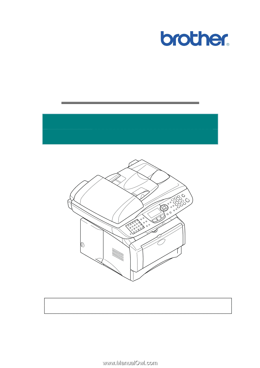
SERVICE MANUAL
MODEL: MFC8440/8840D/8840DN
DCP8040/8045D/8045DN
Read this manual thoroughly before maintenance work.
Keep this manual in a convenient place for quick and easy reference at all times.