Brother International HL 1030 Service Manual
Brother International HL 1030 - B/W Laser Printer Manual
 |
UPC - 012502020134
View all Brother International HL 1030 manuals
Add to My Manuals
Save this manual to your list of manuals |
Brother International HL 1030 manual content summary:
- Brother International HL 1030 | Service Manual - Page 1
R Brother Laser Printer SERVICE MANUAL MODEL: HL-1030/1240/1250/1270N Read this manual thoroughly before maintenance work. Keep this manual in a convenient place for quick and easy reference at all times. September, 1999 SM-PRN001 - Brother International HL 1030 | Service Manual - Page 2
without notice. Trademarks: The brother logo is a registered trademark of Brother Industries, Ltd. Apple, . Hewlett Packard is a registered trademark and HP Laser Jet is a trademark of Hewlett Packard Company trademarks of Microsoft Corporation. Windows is a registered trademark of Microsoft - Brother International HL 1030 | Service Manual - Page 3
of the laser printer (hereinafter referred to as "this machine" or "the printer"). This information is vital to the service technician to maintain the high printing quality and performance of the printer. This service manual covers the HL-1030/1240/1250/1270N printers. This manual consists of - Brother International HL 1030 | Service Manual - Page 4
Supply...2-1 1.2 Environment...2-1 1.3 System Requirements for Brother Printer Solution for Windows 2-1 2. UNPACKING ...2-2 3. INSTALL THE PRINTER 2-3 3.1 For Windows® Users ...2-3 3.2 For Windows® Users with No CD-ROM Drive 2-5 3.2.1 Install the drum unit...2-5 3.2.2 Load paper...2-5 3.2.3 Print - Brother International HL 1030 | Service Manual - Page 5
manual feed slot 2-12 5. CONTROL PANEL OPERATION 2-13 5.1 Ready (Paper) LED Indications 2-13 5.2 Data (Toner) LED Indications 2-14 5.3 Drum LED Indications ...2-14 5.4 Alarm ...3-16 1.3.9 Reset circuit ...3-16 1.3.10 Engine I/O ...3-17 1.4 Engine PCB ...3-18 1.5 BR-net PCB (for HL-1270 only - Brother International HL 1030 | Service Manual - Page 6
FLOW 4-2 3. DISASSEMBLY PROCEDURE 4-3 3.1 AC Cord...4-3 3.2 Drum Unit...4-3 3.3 Paper Cassette ...4-4 3.4 Network Board (for HL-1270N only 4-10 3.5 Front Cover...4-11 3.6 Top Cover ...4-12 3.7 Main Cover ...4-13 3.8 Laser Unit ...4-15 3.9 Drive Unit ...4-16 3.10 Fixing Unit...4-18 3.11 Base Plate - Brother International HL 1030 | Service Manual - Page 7
...5-1 1.2 Toner Cartridge...5-2 2. PERIODICAL REPLACEMENT PARTS 5-4 3. PERIODICAL CLEANING 5-5 3.1 Cleaning the Printer Exterior 5-5 3.2 Cleaning the Drum Unit...5-5 3.3 Cleaning the Scanner Window 5-6 3.4 Cleaning the Electrical Terminals 5-6 4. MTBF / MTTR ...5-7 CHAPTER 6 TROUBLESHOOTING - Brother International HL 1030 | Service Manual - Page 8
later) Peer to Peer (HP JetAdmin Compatible Method) Troubleshooting ...6-49 9.8 Windows 95/98/NT 4.0 Peer to Peer Print (NetBIOS) Troubleshooting 6-49 9.9 Internet Print (TCP/IP) Troubleshooting 6-49 9.10 Novell Netware Troubleshooting 6-50 9.11 AppleTalk Troubleshooting 6-50 9.12 Apple TCP/IP - Brother International HL 1030 | Service Manual - Page 9
of the following labels on the back of the printer indicates compliance with the FDA regulations and must be attached to laser products marketed in the United States. The label for Japanese manufactured products MANUFACTURED: K BROTHER INDUSTRIES, LTD. 15-1, Naeshiro-cho, Mizuho-ku, Nagoya 467 - Brother International HL 1030 | Service Manual - Page 10
LASER PRODUCT APPAREIL LASER DE CLASSE 1 LASER KLASSE 1 PRODUKT This printer has a laser diode which emits invisible laser radiation in the Laser Unit. The Laser in this manual may result in hazardous radiation exposure. For Finland and Sweden LUOKAN 1 LASERLAITE KLASS 1 LASER APPARAT Varoitus! - Brother International HL 1030 | Service Manual - Page 11
werden. Das Gehäuse der Lasereinheit darf nicht geöffnet werden, da sonst Laserstrahlen austreten können. ADDITIONAL INFORMATION When servicing the optical system of the printer, be careful not to place a screwdriver or other reflective object in the path of the - Brother International HL 1030 | Service Manual - Page 12
cautions that must be observed to service the printer properly or prevent damage to the printer. NOTE: Indicates notes and useful tips to remember when servicing the printer. **Listed below are the various kinds of "WARNING" messages included in this manual. WARNING Always turn off the power - Brother International HL 1030 | Service Manual - Page 13
and User-Friendly Operation for Windows The dedicated printer driver for Microsoft Windows 95/98, Windows 3.1 and Windows NT 4.0 are available on the CD-ROM supplied with your printer. You can easily install them into your Windows system using our installer program. The driver supports our - Brother International HL 1030 | Service Manual - Page 14
IBM Proprinter XL. When you use DOS application software or Windows version 3.0 or earlier, you can use any of these emulations to operate the HL-1250/1270N printers. The printers also support autoemulation switching between HP, Brother BR-Script 2 and Epson or HP, BR-Script 2 and IBM. If you want - Brother International HL 1030 | Service Manual - Page 15
(for HL-1270N only) The Brother printer has built in multi protocol network capability as standard. This allows multiple host computers to share the printer on a 10/100Mbit Ethernet network. Any users can print their jobs as if the printer was directly connected to their computer. Users on Windows - Brother International HL 1030 | Service Manual - Page 16
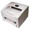
2. OVERVIEW Output tray Tray extension flap Control panel Manual feed paper guides Manual feed slot Paper cassette Fig. 1-1 HL-1030/1240 Front cover Paper indicator Rear cover USB interface connector (for HL-1240 only) Parallel interface connector AC power inlet - Brother International HL 1030 | Service Manual - Page 17
the optional RS-100M) 1200(H) x 600(V) dots/inch (for Windows DIB graphics) 600 x 600 dots/inch (for Windows and DOS) Print quality Normal printing mode Economy printing mode (up to 25% and 50% toner saving) Print speed HL-1030: Up to 10 pages/minute HL-1240/1250/1270N: Up to 12 pages/minute - Brother International HL 1030 | Service Manual - Page 18
1 GENERAL 3.2 Functions CPU Emulation Printer driver Interface Memory Control panel Diagnostics HL-1030/1240: MB86833 66MHz HL-1250/1270N: MB86832 66MHz HL-1030: HL-1240: HL-1250: HL-1270N: Brother Printing Solution for Windows® Brother Printing Solution for Windows® HP LaserJet IIP (PCL level - Brother International HL 1030 | Service Manual - Page 19
less 5 W or less (HL-1030/1240) 6 W or less (HL-1250) 12W or less (HL-1270N) Noise Printing: 49 dB A or less Standing by: 27 dB A or less Temperature Operating: 10 to 32.5°C (50 to 90 and should be used internally at Brother offices only. • The power consumption figure quoted for sleep mode is - Brother International HL 1030 | Service Manual - Page 20
HL-1270N only) Type / Speed 10 HP JetAdmin / Web JetAdmin compatible Firmware update Supplied software 2MB flash ROM. Use BRAdmin32 when upgrading print server software or BOOTP, TFTP PUT/GET or IPX for Netware. • BRAdmin32 management utility (for Windows 95/98/NT 4.0) • Port driver for Windows - Brother International HL 1030 | Service Manual - Page 21
to 6% by weight Cut sheet Basis weight 64 to 158 g/m2 (17 laser label or equivalent • Transparency: 3M CG3300 or equivalent ! CAUTION: When you are choosing print media, be sure to follow the information given below to prevent any paper jams, print quality problems or printer - Brother International HL 1030 | Service Manual - Page 22
10 sheets (2) Paper feed conditions Type Weight Cassette Normal paper (cut sheet) Special paper (cut sheet) 64 to 80 g/m2 158 g/m2 Labels Envelopes Organizers (250 sheet) Manual up the rear cover at the rear of the printer. • Face-down: Delivery with the printed face of the paper downwards - Brother International HL 1030 | Service Manual - Page 23
printing area means the area within which the printing of all the data received without any omissions can be guaranteed. (1) Supported by the engine 208mm (2) Supported by the emulation 4.23mm 25 25 2,400 (80 characters) 4.23mm 3.6.2 Print guaranteed area F E NOTE: • The units in the above - Brother International HL 1030 | Service Manual - Page 24
dots) 279.4 mm 11.0" (3,300 dots) 355.6 mm 14.0" (4,200 dots) 250.0 mm 9.84" (2,952 dots) 266.7 mm 10.5" (3,150 dots) 210.0 mm 8.27" (2,480 dots) 148.5 mm 5.85" (1,754 dots) 116.0 mm 4.57" (1,370 dots on 300 dpi resolution. • Organizer is not supported by any printer emulations (commands). 1-12 - Brother International HL 1030 | Service Manual - Page 25
within ±10% of Brother Printer Solution for Windows Check the following system requirements to setup and operate the printer using Brother Printing Solution for Windows: • IBM PC or compatible with 80486 SX or higher microprocessor • 10MB of space available on your hard disk for the printer driver - Brother International HL 1030 | Service Manual - Page 26
CHAPTER 2 INSTALLATION AND BASIC OPERATION 2. UNPACKING When unpacking the printer, check to see that all of the following components are included in the carton. Printer Paper cassette Drum unit (with Toner cartridge included) Documents CD-ROM Floppy disk Fig. 2-1 NOTE: Components may vary - Brother International HL 1030 | Service Manual - Page 27
the printer driver from the supplied floppy disk. (See Subsection 3.2 'For Windows® Users with No CD-ROM Drive'.) 3.1 For Windows® Users (1) Turn HL-1240 model. They vary depending on the model. (4) Select the model of your printer. (5) Select the language you want, then follow the instructions - Brother International HL 1030 | Service Manual - Page 28
or USB. Fig. 2-5 (9) If you click the NOW button, you can install the printer driver immediately. (10) After the printer driver has been installed, the HL-1030, HL-1240, HL-1250 or HL1270N window will appear. Follow the onscreen messages to complete the installation. Fig. 2-6 Fig. 2-7 If - Brother International HL 1030 | Service Manual - Page 29
the printer driver from the floppy disk. 3.2.1 Install the drum unit (1) Open the front cover. (2) Unpack the drum unit assembly and rock it from side to side 5 or 6 times to distribute the toner evenly inside the cartridge. (Fig. 2-8) Fig. 2-8 (3) Install the drum unit into the printer until - Brother International HL 1030 | Service Manual - Page 30
disk drive. (3) Install the printer driver using the Setup.exe file. In Windows 95/98 i) Click the Start button and select Run. ii) Type A:\SETUP and click OK. (If your floppy disk drive is not A, insert the correct drive letter instead of 'A'.) iii) Follow the instructions that appear on the - Brother International HL 1030 | Service Manual - Page 31
cable to the computer, then connect it to the printer. (Fig. 2-14) USB interface cable 3.3.2 Install the USB driver (1) The "Add New Hardware Wizard" window will appear. Click the Next button. Fig. 2-14 (2) Select "Search for the best driver for your device." Click the Next button. Fig. 2-15 - Brother International HL 1030 | Service Manual - Page 32
(3) Insert the supplied CD-ROM into the CDROM drive and select "CD-ROM drive". Click the Next button. (4) Click the Next button, then the USB driver will be installed. Fig. 2-17 (5) Click the Finish button. Fig. 2-18 (6) Click the Yes button, then your PC will restart. Fig. 2-19 Fig. 2-20 - Brother International HL 1030 | Service Manual - Page 33
Macintosh) with USB Users Only When you use the HL-1240/1250/1270N printer with Macintosh using USB, setup the printer following the Initial Setup instructions on the supplied CD-ROM. (1) Turn on the computer power, then insert the CD-ROM into the CD-ROM drive. The window shown below will appear - Brother International HL 1030 | Service Manual - Page 34
below; (1) Select the manual feed mode in the printer driver, and send the print data to the printer. NOTE: A 'NO PAPER' message is shown in the status monitor until a sheet of paper is inserted into the manual feed slot. (2) Set the width of the manual feed slot paper guides using both hands to - Brother International HL 1030 | Service Manual - Page 35
Side Printing (Manual Duplexing) The supplied printer driver allows you to do manual duplex printing. When using the manual duplex function, note and the top edge toward you. Follow the instructions on the computer screen. (Fig. 226) (5) The printer will now automatically print all the odd pages on - Brother International HL 1030 | Service Manual - Page 36
pages from the output tray (5) Re-insert them in order into the manual feed slot, loading the paper with the side to be printed (blank side) face up, and the top edge towards the printer. Follow the instructions on the computer screen. (Fig. 2-27) (6) Repeat action (5) until you have printed - Brother International HL 1030 | Service Manual - Page 37
There are four LEDs and a button on the control panel. The LEDs indicate the printer status, and pressing the button enables several functions in the printer. LEDs Drum Ready Paper Alarm Toner Data Control Panel Button Fig. 2-28 5.1 Ready (Paper) LED Indications The Ready LED indicates - Brother International HL 1030 | Service Manual - Page 38
empty. Purchase a new toner cartridge ready for when the 'Toner empty' error is indicated. Toner empty Replace the toner cartridge with a new one. 5.3 Drum LED Indications The Drum LED indicates the drum unit is nearly at the end of its life. LED Printer status OFF The drum unit can be used - Brother International HL 1030 | Service Manual - Page 39
10 minutes whenever printing finishes. 2) The fan runs while the printer is in ready status. 3) The fan runs for at least 5 minutes after the printer the printer is warming up. • You can change the timeout for the sleep mode with the supplied printer driver (all models) or Remote Printer Console - Brother International HL 1030 | Service Manual - Page 40
CHAPTER 2 INSTALLATION AND BASIC OPERATION 5.6.2 Test print mode The printer incorporates various test print modes. The printer enters into each test print mode by panel button operation. For details on test print mode, see Subsection 10.1 'Test Print Mode' in CHAPTER 6. 2-16 - Brother International HL 1030 | Service Manual - Page 41
, refer to the Network User's Guide on the supplied CDROM. (1) Insert the supplied CD-ROM into your CD-ROM drive. (2) Select the HL-1270N model button and follow the screen instructions. (3) The BRAdmin32 utility will then be installed onto your computer. When the software is installed, re-boot - Brother International HL 1030 | Service Manual - Page 42
This LED will blink as the print server receives or transmits data. 6.2.2 Factory default setting If you wish to reset the print server back to its default factory settings (resetting all information such as the password and IP address information), hold down the Network Test button for more than - Brother International HL 1030 | Service Manual - Page 43
/1240 printer. Control system RAM 2MB Video control block Interface block (HL-1030: Parallel) (HL1240: Parallel/USB) External device Low-voltage power supply block High-voltage power supply block Engine control block Operation block (Control panel) Laser unit Drive block (DC motor) Drum - Brother International HL 1030 | Service Manual - Page 44
control block Operation block (Control panel) Laser unit Drive block (DC motor) Drum unit Transfer block Charging block Drum Paper dust cleaner block Developing block Toner cartridge Image generation system Paper tray unit Paper cassette Manual feed Fixing unit Paper eject block Paper - Brother International HL 1030 | Service Manual - Page 45
control block Operation block (Control panel) Laser unit Drive block (DC motor) Drum unit Transfer block Charging block Drum Paper dust cleaner block Developing block Toner cartridge Image generation system Paper tray unit Paper cassette Manual feed Fixing unit Paper eject block Paper - Brother International HL 1030 | Service Manual - Page 46
PCB of the HL-1030/1240 printer. A S I C Reset Circuit CPU Core (MB86833) BUS INT Oscillator (32.7MHz) Program + Font ROM 1.0 Mbytes Address Decoder DRAM Control RAM (2.0 Mbytes) Timer FIFO CDCC Parallel I/O To PC USB I/O (HL-1240 only) To PC Soft Support EEPROM (128 8 bits) EEPROM - Brother International HL 1030 | Service Manual - Page 47
Fig. 3-5 shows the block diagram of the main PCB of the HL-1250 printer. A S I C Reset Circuit CPU Core (MB86832) BUS INT Oscillator (32.7MHz) Program + Font ROM 4.0 Mbytes RAM (4.0 Mbytes) Option RAM (SIMM) (max. 32Mbytes) Address Decoder DRAM Control Timer - Brother International HL 1030 | Service Manual - Page 48
PCB of the HL-1270N printer. Reset Circuit CPU Core (MB86832) BUS INT A S I C Oscillator (32.7MHz) Program + Font ROM 4.0 Mbytes Flash ROM (2.0 Mbytes) RAM (4.0 Mbytes) Address Decoder DRAM Control Timer FIFO CDCC Parallel I/O Option RAM (SIMM) (max. 32Mbytes) USB I/O Soft Support To PC To - Brother International HL 1030 | Service Manual - Page 49
HL-1030/1240 A Fujitsu 32bit RISC CPU, MB86833 (SPARC lite) is built in the ASIC. While the CPU is driven with a clock frequency of 33 MHz in the user communication (nibble mode, byte mode, ECP mode). (2) USB interface (for HL-1240 only) Stores the data received from the PC into DRAM as controlled - Brother International HL 1030 | Service Manual - Page 50
CHAPTER 3 THEORY OF OPERATION HL-1250/1270N A Fujitsu 32bit RISC CPU, MB86832 (SPARC lite) is built in the ASIC. While the CPU is driven with a clock frequency of 33 MHz in the user logic block, it itself runs at 66 MHz, which is generated by multiplying the source clock by two. The functions - Brother International HL 1030 | Service Manual - Page 51
CHAPTER 3 THEORY OF OPERATION Fig. 3-8 3-9 - Brother International HL 1030 | Service Manual - Page 52
CHAPTER 3 THEORY OF OPERATION 1.3.2 ROM HL-1030/1240 An 8 Mbits ROM (x 16 bit) is fitted. Fig. 3-9 HL-1250 Two 16 Mbits ROMs (x 16 bit) are fitted. Fig. 3-10 3-10 - Brother International HL 1030 | Service Manual - Page 53
HL-1270N Two 32 Mbits ROMs (x 16 bit) are fitted. CHAPTER 3 THEORY OF OPERATION Fig. 3-11 3-11 - Brother International HL 1030 | Service Manual - Page 54
CHAPTER 3 THEORY OF OPERATION 1.3.3 Flash ROM (for HL-1270N only) HL-1270N Two 8 Mbits flash ROMs (x 16 bit) are fitted. Fig. 3-12 1.3.4 DRAM HL-1030/1240 A 16M-bit DRAM (x 16 bits) is used as the RAM. Fig. 3-13 3-12 - Brother International HL 1030 | Service Manual - Page 55
HL-1250/1270N Two 16M-bit DRAMs (x 16 bits) are used as the RAM. CHAPTER 3 THEORY OF OPERATION Fig. 3-14 3-13 - Brother International HL 1030 | Service Manual - Page 56
CHAPTER 3 THEORY OF OPERATION 1.3.5 Optional RAM HL-1250/1270N A 32bit (72 pin) SIMM can be fitted as optional RAM. The main PCB has one slot and the capacity of SIMM can be from 1 Mbyte to 32 Mbytes. Fig. 3-15 3-14 - Brother International HL 1030 | Service Manual - Page 57
recognized by the CPU. A 32-byte register is provided for this I/O, which is read from and written to by the CPU. Fig. 3-16 1.3.7 PCI bus HL-1270N The interface of the PCI bus is PCI specification revision 2.2 compliant. Fig. 3-17 3-15 - Brother International HL 1030 | Service Manual - Page 58
is X24C04 type of two-wire method with a 512 x 8 bits configuration. Fig. 3-19 HL-1270N The EEPROM is X24C32 type of two-wire method with a 4096 x 8 bits configuration. Fig. 3-20 1.3.9 Reset circuit HL-1030/1240 The reset IC is a RN5VD42A. The reset voltage is 4.2V (typ.) and the LOW period of - Brother International HL 1030 | Service Manual - Page 59
voltage is 4.2V (typ.) and the LOW period of reset is 80ms (typ.) Fig. 3-22 1.3.10 Engine I/O HL-1030/1240 Fig. 3-22 shows the engine interface circuit. The interface with the engine PCB is by fullduplex synchronous serial method. Fig. 3-23 HL-1250/1270N Fig. 3-23 shows the engine interface circuit - Brother International HL 1030 | Service Manual - Page 60
using the transferred signal data; • Main motor • Toner sensor • Panel PCB • Cover sensor • Fan , see Appendix 18. 1.5 BR-net PCB (for HL-1270N only) The BR-net PCB is connected to on the BR-net PCB. The controller incorporates the 10/100 Mbps physical interface which conforms to IEEE 802.3 - Brother International HL 1030 | Service Manual - Page 61
CHAPTER 3 THEORY OF OPERATION 1.6 Power Supply 1.6.1 Low-voltage power supply The power supply uses a switching regulation system to generate the regulated DC power (+5V and +24V), which are converted from the AC line. The regulated output and the production code of each power supply are listed - Brother International HL 1030 | Service Manual - Page 62
Current Regulator B1 Voltage Regulator VR22 Current Regulator B102 Q81 Voltage Regulator B101 Q101 Voltage Regulator Z51 VR51 Supply Roller Transfer Roller Development Roller Photosensitive Drum Corona Unit Fig. 3-26 3-20 - Brother International HL 1030 | Service Manual - Page 63
2.1 Overview of Printing Mechanism Second eject roller Photosensitive drum Thermistor Cleaner Corona wire Laser Unit Polygon mirror Scanner motor Rear cover Heat roller First eject roller Drum Unit Development roller Blade Agitator Toner sensor Supply roller Paper feed roller Fixing Unit - Brother International HL 1030 | Service Manual - Page 64
Sensor (HL-1250/1270N) HighVoltage Power Supply PCB Cover Sensor (B) Drum Unit Primary Charger (Corona Wire) Primary Charger (Grid) Development Roller Supply Roller Transfer Roller Solenoid Fan Motor Main Motor Toner Sensor PCB (light emission) Toner Sensor PCB (light reception) Thermistor - Brother International HL 1030 | Service Manual - Page 65
. Then, the solenoid is turned off, the paper feed roller starts turning, and the paper is fed to the transfer block in the drum unit. Photosensitive drum Paper feed roller Transfer roller Rear registration sensor lever Fig. 3-30 The rear registration sensor in the path from the feed roller to the - Brother International HL 1030 | Service Manual - Page 66
image on the photosensitive drum is transferred onto the paper, the paper is fed to the fixing unit to fix unfixed toner onto the paper. Afterwards rear cover is open, the paper is ejected face up straight to the printer rear (straight paper path). Second eject roller Rear cover First eject roller - Brother International HL 1030 | Service Manual - Page 67
is toner in the toner cartridge. The toner sensor at the left side emits light through the window on the left side of the toner cartridge, then the toner sensor at the right side receives it when the toner is low. They also detect whether or not the drum unit is installed. (The toner cartridge is - Brother International HL 1030 | Service Manual - Page 68
expelled from the printer is therefore not harmful to the human body. Applicable safety standards have been complied with. 2.6.2 Exposure stage After the drum is positively charged, it is exposed to the light emitted from the laser unit. Drum Laser beam Laser detector Paper Laser beam f θ lens - Brother International HL 1030 | Service Manual - Page 69
(a) +420 (b) +200 1 Primary charging 2 Laser beam exposure and developing (a) Unexposed area ( Non image area ) (b) Exposed area ( Image area ) 3 Transfer the image to paper Drum Sleeve 0 Time Fig. 3-36 2.6.3 Developing Developing causes the toner to be attracted to the electrostatic image on - Brother International HL 1030 | Service Manual - Page 70
transferred onto the paper by applying a negative charge to the back of the paper. The negative charge applied to the paper causes the positively charged toner to leave the drum, and adhere to the paper. As a result, the image is visible on the paper. (2) Cleaning process of transfer roller If the - Brother International HL 1030 | Service Manual - Page 71
AND RE-ASSEMBLY 1. SAFETY PRECAUTIONS To avoid creating secondary problems by mishandling, follow the warnings and precautions below during before accessing any parts inside the printer. (2) Some parts inside the printer are extremely hot immediately after the printer is used. When opening the front - Brother International HL 1030 | Service Manual - Page 72
TRAY RELAY PCB ASSY (HL-1250/1270N only) LOW-VOLTAGE PS PCB ASSY 15 ENGINE PCB ASSY / HIGH-VOLTAGE PS PCB ASSY 16 PANEL PCB ASSY B 19 17 TONER SENSOR PCB ASSY (emission) SOLENOID ASSY A 20 TONER SENSOR PCB ASSY (reception) 18 FAN MOTOR 8 LASER UNIT 9 DRIVE UNIT 10 FIXING UNIT A 22 - Brother International HL 1030 | Service Manual - Page 73
CHAPTER 4 DISASSEMBLY AND RE-ASSEMBLY 3. DISASSEMBLY PROCEDURE 3.1 AC Cord (1) Disconnect the AC cord from the printer AC inlet. Printer AC cord Fig. 4-1 3.2 Drum Unit (1) Open the front cover and remove the drum unit from the printer. Drum unit Fig. 4-2 4-3 - Brother International HL 1030 | Service Manual - Page 74
CHAPTER 4 DISASSEMBLY AND RE-ASSEMBLY 3.3 Paper Cassette (1) Close the front cover, pull out the paper cassette from the printer and remove the paper from the cassette. Front cover Paper cassette Fig. 4-3 (2) Remove the separation pad holder ASSY by pulling it upwards, then remove the - Brother International HL 1030 | Service Manual - Page 75
screw securing the paper cassette cover indicated RED in the figure above is very special. When disassembling/re-assembling the screw, you need a special screw driver. Refer to the parts reference list. 4-5 - Brother International HL 1030 | Service Manual - Page 76
Pressure roller holder Fig. 4-7 (8) Keeping the paper cassette upside down, remove the two M2.6x5 Taptite screws. (9) Unhook the catches of each side guide, then press the lock lever towards the front of the cassette to release the pressure plate. Taptite, cup M2.6x5 Taptite, cup M2.6x5 Side - Brother International HL 1030 | Service Manual - Page 77
CHAPTER 4 DISASSEMBLY AND RE-ASSEMBLY (10) Turn the cassette the correct way up and slide the two paper guides to the center of the cassette. (11) Remove the side guides Left and Right from the paper cassette. Side guide L Side guide R ➁ ➀ Paper cassette Fig. 4-9 (12) Unhook the two catches (A) - Brother International HL 1030 | Service Manual - Page 78
plate, gently ease the plastic cover. If the pressure plate is deformed, paper feeding problems may occur. (14) Remove the release lever extension spring. (15) Unhook the two (16) Slide the rear paper guide fully forwards in the cassette and remove it from the slot. ➁ ➀ ➂ Paper cassette Rear - Brother International HL 1030 | Service Manual - Page 79
, they should both be aligned so that the wide end of the racks are in line with the inside edge of the paper guide release slots in the cassette before refitting the spring and gear. • When replacing/re-assembling the paper cassette, remove the old grease and apply a suitable - Brother International HL 1030 | Service Manual - Page 80
CHAPTER 4 DISASSEMBLY AND RE-ASSEMBLY 3.4 Network Board (for HL-1270N only) (1) Open the rear cover. (2) Remove the two M3x8 Taptite screws to remove the access cover. Rear cover the connector connected with the main PCB and remove the network board. Network board Taptite, cup M3x6 Fig. 4-16 4-10 - Brother International HL 1030 | Service Manual - Page 81
CHAPTER 4 DISASSEMBLY AND RE-ASSEMBLY 3.5 Front Cover (1) Open the front cover. (2) Remove the four M3x8 Taptite screws from the main cover. Taptite, bind M3x8 Front cover Main cover Taptite, bind M3x8 Fig. 4-17 (3) Position the front cover at the angle of 45 degrees and release the bosses at - Brother International HL 1030 | Service Manual - Page 82
rear cover, then release the hooks (A) at the right and left hand sides of the top cover while pushing them towards the side of the printer from the rear. (4) Lift up the top cover and release the hooks (B) at the right and left hand sides of the top cover to remove - Brother International HL 1030 | Service Manual - Page 83
the two M3x8 Taptite screws from the rear of the main cover. (2) Release the hooks at the right and left hand top sides of the printer, then, while pulling the cover outwards to clear the power socket and switch, lift up the main cover to remove it complete with the rear - Brother International HL 1030 | Service Manual - Page 84
CHAPTER 4 DISASSEMBLY AND RE-ASSEMBLY (3) Bend the tray extension flap upwards slightly to remove the tray extension flap. Tray extension flap ➁ ➀ Main cover Fig. 4-23 (4) Release the rear cover springs Left and Right from the hooks on the main cover. (5) Remove the rear cover complete with the - Brother International HL 1030 | Service Manual - Page 85
dirt or dust on the window, blow it off using an air gun. If cleaning the underside of the scanner window, wipe off dirt or dust with soft clean paper. Refer to subsection 3.3 'Cleaning the Scanner Window' in CHAPTER 5. Laser unit Reflect mirror Scanner window Printer body Lens Fig. 4-26 4-15 - Brother International HL 1030 | Service Manual - Page 86
printer body carefully on its right hand side so that the drive unit is at the top. (2) Remove the five M3x6 Taptite screws securing the gear plate. (3) Disconnect the heater harness connector and release the panel PCB harness from the hooks. (4) Carefully lift the drive unit and while supporting - Brother International HL 1030 | Service Manual - Page 87
CHAPTER 4 DISASSEMBLY AND RE-ASSEMBLY NOTE: When replacing/re-assembling the main motor, remove the old grease and apply a suitable amount of grease referring to the figure below; Main motor ASSY Grease: Molykote PG-662 (1 rice-grain size) Fig. 4-29 (7) Remove the development joint complete with the - Brother International HL 1030 | Service Manual - Page 88
CHAPTER 4 DISASSEMBLY AND RE-ASSEMBLY 3.10 Fixing Unit (1) Place the main frame on its base so that the rear side is facing you. (2) Press the two hooks inwards to remove gear - Brother International HL 1030 | Service Manual - Page 89
CHAPTER 4 DISASSEMBLY AND RE-ASSEMBLY NOTE: When re-assembling the fixing unit, align the fixing unit frame at the drive unit side into the concave part of the main frame. Fixing unit Main frame Main frame (concavity) Fixing unit Fig. 4-33 (7) Remove the M3x10 screw to remove the star wheel - Brother International HL 1030 | Service Manual - Page 90
DISASSEMBLY AND RE-ASSEMBLY (8) Remove the two M3x20 Taptite screws from the top of the fixing unit frame. (9) Release the thermistor harness from the hooks. (10) Release the two hooks at the right and left sides securing the fixing unit cover to the fixing unit frame. (hook) (hook) Taptite, cup - Brother International HL 1030 | Service Manual - Page 91
CHAPTER 4 DISASSEMBLY AND RE-ASSEMBLY (12) Remove the one M3x10 Taptite screw securing the halogen lamp connector plate at the drive unit side of the fixing unit frame and then loosen the M3x6 screw at the other side. (13) Lift the right hand end of the heat roller and remove the halogen heater - Brother International HL 1030 | Service Manual - Page 92
CHAPTER 4 DISASSEMBLY AND RE-ASSEMBLY (14) Lift and remove the heat roller. The heat roller gear will also come off. (15) Remove the heat roller bearing from the left hand end of the heat roller. To remove the bearing at the gear side, first remove the two washers, then remove the bearing. Heat - Brother International HL 1030 | Service Manual - Page 93
CHAPTER 4 DISASSEMBLY AND RE-ASSEMBLY • When re-assembling the heat roller bearing which is assembled at the heat roller gear side, fix the bearing onto the heat roller so that the embossment whose thickness is 0.5mm is at the top. Heat roller gear Heat roller bearing Heat roller (embossment) - Brother International HL 1030 | Service Manual - Page 94
CHAPTER 4 DISASSEMBLY AND RE-ASSEMBLY (16) Remove the heat roller cleaner complete with the cleaner spring from the fixing unit frame by lifting it upwards until the spring releases from the frame. (17) Remove the cleaner spring from the heat roller cleaner. Heat roller cleaner Cleaner spring - Brother International HL 1030 | Service Manual - Page 95
CHAPTER 4 DISASSEMBLY AND RE-ASSEMBLY NOTE: • When re-assembling the pressure roller cleaner complete with the cleaner spring onto the fixing unit cover, ensure the direction of the roller is correct referring to the figure above. • Ensure also that the spring is seated correctly in the locating - Brother International HL 1030 | Service Manual - Page 96
CHAPTER 4 DISASSEMBLY AND RE-ASSEMBLY (22) Press the two catches holding the idle gear 13 to the frame and then remove the idle gear 13. Slide the first eject roller to the left until the slot in the roller shaft aligns with the slot in the frame and then remove the roller by pulling it forwards. - Brother International HL 1030 | Service Manual - Page 97
CHAPTER 4 DISASSEMBLY AND RE-ASSEMBLY PR2000057 (24) Turn the frame up-side down. Remove the black films (4 pcs.) and then remove the pick off fingers (4 pcs.) using a piece of tweezers. Pick off finger Tweezers Film Pick off finger Fig. 4-48a (25) Release the paper eject actuator from the hook - Brother International HL 1030 | Service Manual - Page 98
CHAPTER 4 DISASSEMBLY AND RE-ASSEMBLY PR2000057 NOTE: When re-assembling the paper eject actuator and the eject paper spring to the fixing unit cover, ensure the paper eject actuator is seated correctly in the locating channel referring to the figure below; Paper eject actuator Fixing unit cover - Brother International HL 1030 | Service Manual - Page 99
from the base plate. (3) Slide the base plate to the rear of the printer to remove it. ! CAUTION: Do not remove the ground wire connected to the supply unit. Unnecessary disconnection of the ground wire may cause increased printer noise. Taptite, bind M4x10 Taptite, bind M3x8 Taptite, bind M3x8 - Brother International HL 1030 | Service Manual - Page 100
CHAPTER 4 DISASSEMBLY AND RE-ASSEMBLY ! CAUTION: • When re-assembling the base plate, be sure that the ground wire connected to the paper feed roller ASSY is fixed into the slit on the plastic chute referring to the figure below; Ground wire Plastic chute (slit) Fig. 4-49 Main frame • When - Brother International HL 1030 | Service Manual - Page 101
Main PCB LD connector Engine PCB connector Low-voltage power supply connector ➁ ➀ Screw M3x8 I/F plate Fig. 4-51 3.13 Lower Tray Relay PCB ASSY (for HL-1250/1270N only) (1) Remove the M3x6 Taptite screw and remove the lower tray relay PCB ASSY. Main frame Taptite, cup M3x6 Lower tray relay PCB - Brother International HL 1030 | Service Manual - Page 102
CHAPTER 4 DISASSEMBLY AND RE-ASSEMBLY 3.14 Low-Voltage Power Supply PCB ASSY (1) Remove the M3x8 Taptite screw to remove the insulation sheet. (2) Slightly lift up the low-voltage power supply PCB ASSY from the frame and disconnect the engine PCB connector. Then lift the power supply PCB ASSY - Brother International HL 1030 | Service Manual - Page 103
the AC inlet ASSY in the following cases referring to the figure below; • If the film is not attached to the AC inlet on the printer you are servicing. • If the film is damaged, or the adhesive is weak. AC inlet ASSY Film Fig. 4-55a 4-30A - Brother International HL 1030 | Service Manual - Page 104
CHAPTER 4 DISASSEMBLY AND RE-ASSEMBLY 3.15 Engine PCB ASSY / High-Voltage Power Supply PCB ASSY (1) Remove the M4x12 Taptite screw to remove the insulation sheet. (2) Remove the three M4x12 Taptite screws securing the engine PCB and the high-voltage power supply PCB. (3) Lift the engine PCB and - Brother International HL 1030 | Service Manual - Page 105
CHAPTER 4 DISASSEMBLY AND RE-ASSEMBLY (5) Disconnect the 11 (eleven) connectors for HL-1030/1240 or 12 (twelve) connectors for HL1250/1270N from the engine PCB to remove the engine PCB ASSY. Toner sensor (light reception) connector Low-voltage power supply connector (for HVPS) Main PCB connector - Brother International HL 1030 | Service Manual - Page 106
CHAPTER 4 DISASSEMBLY AND RE-ASSEMBLY 3.16 Panel PCB ASSY NOTE: Be sure to remove the drive unit and disconnect the panel PCB connector on the engine PCB before removing the panel PCB ASSY. (1) Remove the M3x6 Taptite screw, then remove the panel PCB ASSY. Panel PCB Fig. 4-57 Taptite, cup M3x6 - Brother International HL 1030 | Service Manual - Page 107
CHAPTER 4 DISASSEMBLY AND RE-ASSEMBLY (4) Release the catch and remove the clutch levers for the feed roller and pick-up roller. Clutch lever spring Clutch lever (for paper feed roller) Rod Clutch lever (for paper feed roller) Clutch lever (for paper pick-up roller) Solenoid Clutch lever (for - Brother International HL 1030 | Service Manual - Page 108
upside down. (7) Remove the two M3x6 Taptite screws and release the solenoid harness from the hook and remove the cassette guide L/F. Step (7) Taptite, cup M3x6 Cassette guide L/F Fig. 4-61 (8) Remove the M3x4 screw and the tape on the solenoid harness and remove the solenoid ASSY. Main frame - Brother International HL 1030 | Service Manual - Page 109
-assembling the fan motor, fix the harness into the groove on the motor, then fix the motor onto the bosses. Fan cover Fan motor Fig. 4-64 4-36 (groove) - Brother International HL 1030 | Service Manual - Page 110
on the engine PCB before removing the toner sensor PCB ASSY (light emission). (1) Release the hooks of the toner sensor PCB ASSY (light emission) and remove it. Toner sensor PCB ASSY (light emission) (hooks) (hook) Fig. 4-65 3.20 Toner Sensor PCB ASSY (Light Reception) NOTE: Be sure to disconnect - Brother International HL 1030 | Service Manual - Page 111
CHAPTER 4 DISASSEMBLY AND RE-ASSEMBLY 3.21 Paper Pick-up Roller ASSY NOTE: Be sure to remove all the covers and the base plate before removing the paper pick-up roller ASSY. (1) Place the main frame upside down. (2) Unhook the hook to remove the inner gear 54, gear 45 and gear 20 from the main - Brother International HL 1030 | Service Manual - Page 112
CHAPTER 4 DISASSEMBLY AND RE-ASSEMBLY 3.22 Paper Feed Roller ASSY NOTE: Be sure to remove all the covers and the PCBs before removing the paper feed roller ASSY. (1) Unhook the black plastic hook on the shaft to remove gear 21. Gear 21 (hook) Fig. 4-69 ! CAUTION: The plastic hook holding gear 21 - Brother International HL 1030 | Service Manual - Page 113
CHAPTER 4 DISASSEMBLY AND RE-ASSEMBLY PR2000051 3.23 Outer Chute 1 (1) Remove two M3x6 Taptite screws and two M3x8 Taptite screws to remove the outer chute 2 ASSY. (2) Unhook two hooks using a slotted screwdriver and then remove the outer chute 1. Outer chute 1 Outer chute 2 ASSY Fig. 4-70a 4- - Brother International HL 1030 | Service Manual - Page 114
CHAPTER 4 DISASSEMBLY AND RE-ASSEMBLY 4. PACKING Insertion sheet Accessory bag Accessory carton Pad Printer Carton AC Cord Drum Unit (with Toner Cartridge included) Pad Fig. 4-71 4-40 - Brother International HL 1030 | Service Manual - Page 115
warranty of the product if any print quality problem appears. 1.1 Drum Unit The Drum LED is on when the drum unit is nearly at the end of its of the printer and pull out the drum unit. (2) Place the drum unit on a flat, horizontal surface, and remove the toner cartridge from the drum unit while - Brother International HL 1030 | Service Manual - Page 116
unit immediately before you need to install it into the printer. If an unpacked drum unit is subjected to excessive direct sunlight or room light, the unit may be damaged. • Handle the drum unit and toner cartridge carefully. If toner scatters on your hands or clothes, wipe or wash it off with cold - Brother International HL 1030 | Service Manual - Page 117
quality but also the quality and life of the printer itself. It may also cause serious damage to the performance and life of a genuine Brother drum unit. Warranty cover is not applied to problems caused by the use of 3rd party toner or toner cartridges. • Make sure that the wire cleaner on the - Brother International HL 1030 | Service Manual - Page 118
be damaged or there is no change in their appearance.) The periodical replacement parts listed below should be replaced at the service center referring to the service life. For the procedures to replace these parts, refer to CHAPTER 4 "DISASSEMBLY AND RE-ASSEMBLY". Parts Name Part No. Fixing Unit - Brother International HL 1030 | Service Manual - Page 119
to avoid any printer problems or print image defects. ! CAUTION: While drum unit and scanner window cleaning basically can be implemented by the end user, the electrical terminals inside the printer and on the drum unit should be cleaned by a service technician. Instruct the users not to touch - Brother International HL 1030 | Service Manual - Page 120
MAINTENANCE 3.3 Cleaning the Scanner Window When replacing the drum unit or toner cartridge with a new one, be sure to clean the scanner window. 1) Turn off the power switch and unplug the power cord. 2) Remove the drum unit from the printer. 3) Gently wipe the scanner window (colored magenta in the - Brother International HL 1030 | Service Manual - Page 121
CHAPTER 5 PERIODIC MAINTENANCE 4. MTBF / MTTR The meantime between failure (MTBF) and the meantime to repair (MTTR) for this printer are as follows; MTBF: Up to 4,000 hours MTTR: Average 30 minutes 5-7 - Brother International HL 1030 | Service Manual - Page 122
CHAPTER 5 PERIODIC MAINTENANCE 5-8 - Brother International HL 1030 | Service Manual - Page 123
paper. [If so, print quality problems may occur.] For further information on paper, refer to subsection 3.5 'Paper' in CHAPTER 1. (3) Consumable parts Check if : • The Toner LED is not lit on the printer control panel when a toner cartridge is installed in the printer. [If the LED is lit, replace - Brother International HL 1030 | Service Manual - Page 124
, print several pages or leave the printer for 2 hours to allow it to reach room temperature. If the drum unit is unpacked soon after it is moved from a cold room to a warm room, condensation may occur inside the unit, which may cause incorrect images. Instruct the user to allow the unit to come to - Brother International HL 1030 | Service Manual - Page 125
see the appropriate section. NOTE: The following troubleshooting sections contain both the actions which users should take or check and the ones which service technicians should perform. The printer does not print. Printed page has a problem. LED is blinking. 2.1 'Operator Calls' Printed image - Brother International HL 1030 | Service Manual - Page 126
the toner cartridge with a new one. 2.2 Service Calls When the printer indicates the need for a service call by illuminating all the LEDs and then a combination of LEDs alternately as shown in the table on the next page, a user unrecoverable error may have occurred. Instruct the user to turn - Brother International HL 1030 | Service Manual - Page 127
CHAPTER 6 TROUBLESHOOTING PR99180 Type of error Fuser Malfunction Laser BD Malfunction Scanner Malfunction ROM Error D-RAM Error Service A * Service B * Engine Interface Error Main Motor Malfunction NV-RAM Error CPU Runtime Error * PCI Bus Error Drum Ready Alarm Data Remedy See 'M-9 Fuser - Brother International HL 1030 | Service Manual - Page 128
of the document or reduce the print resolution. (3) (For HL-1250/1270N only) Expand the printer memory by adding a commercially available SIMM. Set page protection to ON by using the supplied Windows driver or RPC program. (4) (For HL-1250/1270N only) Change the following settings in the supplied - Brother International HL 1030 | Service Manual - Page 129
TROUBLESHOOTING Error Message Remedy FUSER MALFUNCTION Turn the power switch off, wait a few seconds and then turn it on again. Leave the printer for 10 minutes with power on. If the same error occurs again, see 'M-9 Fuser failure'. LASER error occurs again, see 'M-10 ROM error / D-RAM error - Brother International HL 1030 | Service Manual - Page 130
CHAPTER 6 TROUBLESHOOTING 3.2 Error Message Printouts The printer will report problems by printing an error message HL-1250/1270N only) Expand the printer memory by adding a commercially available SIMM. Set page protection to ON by using the supplied Windows driver or RPC program. (4) (For HL- - Brother International HL 1030 | Service Manual - Page 131
mode is not selected in the printer driver. (1) Re-install the paper firmly into the manual feed slot, one sheet at a time. (2) Check that manual feed mode is selected in the printer driver. Check that envelopes are loaded into the manual feed slot. The application software must be set up correctly - Brother International HL 1030 | Service Manual - Page 132
6 TROUBLESHOOTING 4.2 Paper Jams 4.2.1 Clearing jammed paper Clear the jammed paper following the procedures below; (1) Remove the paper cassette completely from the printer. (2) Pull any jammed paper up and out of the printer.(Fig. 6-2) (3) Open the front cover. Fig. 6-2 (4) Remove the drum unit - Brother International HL 1030 | Service Manual - Page 133
: How to check the sensors: 1) Turn off the printer power switch, open the front cover, and remove the drum unit. 2) Turn on the printer while pressing the control panel button. The Drum LED comes ON. 3) Lightly press the panel button again. Alarm LED is ON = Front registration sensor is turned ON - Brother International HL 1030 | Service Manual - Page 134
° in the cassette. Possible cause Paper Step 1 Check Is the problem solved if new paper is used? Fixing unit entrance guide Fixing unit 2 Is the entrance guide dirty? 3 Is the pressure roller dirty? Result Yes Yes Remedy Instruct the user how to store paper so that it does not absorb moisture - Brother International HL 1030 | Service Manual - Page 135
CHAPTER 6 TROUBLESHOOTING F-3 Page skew User Check (1) Check that the paper or other media is loaded into the paper cassette correctly and that the paper guides are not too tight or too loose against the paper stack. (2) If using the manual feed slot, check how to load paper into the manual feed - Brother International HL 1030 | Service Manual - Page 136
CHAPTER 6 TROUBLESHOOTING 5. SOFTWARE SETTING PROBLEMS The printer may not print the data correctly if there are incorrect software settings. S-1 "There was an error writing to LPT1: (or BRUSB) for the printer" error message appears. User Check (1) Check that the printer cable is not damaged or - Brother International HL 1030 | Service Manual - Page 137
print from application software under DOS. User Check (1) Check that the DOS application software interface settings match that of your printer. (2) Check if the printer has any printer alarms active. (3) Check if the appropriate printer is selected in your application software. (4) (HL-1250 only - Brother International HL 1030 | Service Manual - Page 138
CHAPTER 6 TROUBLESHOOTING S-4 Unable to print from application software with an Apple Macintosh Computer. (HL-1250 only) User Check (1) Check that the supplied Macintosh printer driver is installed in the System Folder and it is selected with Chooser. (2) Check the PORT selection within the - Brother International HL 1030 | Service Manual - Page 139
CHAPTER 6 TROUBLESHOOTING S-6 This printer does not appear in Chooser with iMac and Power Macintosh G3 with USB. (HL-1240/1250/1270N only) User Check (1) Check the printer is turned on. (2) Check the USB interface cable is connected correctly. (3) Check the printer driver is installed correctly. - Brother International HL 1030 | Service Manual - Page 140
6 TROUBLESHOOTING 6. and the power plug? Result No No Yes Yes Remedy Inform the user that the correct voltage is not supplied at the outlet. Plug the the table below? PCB + lead pin - lead pin Voltage P5-2 Engine P3-10 P5-3 P3-9 Approx. 24V Approx. 5V Result No Yes No Remedy Follow the - Brother International HL 1030 | Service Manual - Page 141
TROUBLESHOOTING M-3 Main motor does not rotate Possible cause Failure of connector Main motor Engine PCB Main PCB Step 1 2 3 4 Check Is the connection of connector P9 on the engine PCB correct? Is the problem solved by replacing the main motor? Is the problem paper in the manual paper slot and - Brother International HL 1030 | Service Manual - Page 142
CHAPTER 6 TROUBLESHOOTING M-5 Insufficient output from high-voltage power supply unit Possible cause High-voltage contact High-voltage power supply PCB Step 1 Is connector P10 on the main PCB secured correctly? Result No Remedy Reconnect the connector securely. Yes Replace the laser unit. 6-20 - Brother International HL 1030 | Service Manual - Page 143
TROUBLESHOOTING low-voltage power supply PCB. Yes Replace the laser unit. M-9 Fuser failure Possible cause Poor thermistor problem will be cleared if leaving the printer power ON for ten minutes. • If the heater is cooled down sufficiently, this problem may be cleared by turning on the printer - Brother International HL 1030 | Service Manual - Page 144
, printer condition and system environment. M-11 Service A (Address error) / Service B (BUS error) / CPU runtime error Possible cause Main PCB Software bug Step 1 2 Check Is it possible to print the test page with the method of Subsection 10.1 'Test Print Mode' in this chapter? Does this problem - Brother International HL 1030 | Service Manual - Page 145
Examples CHAPTER 6 TROUBLESHOOTING I-1 Light I-2 Dark I-3 Completely blank I-4 All black I-5 Dirt on back of paper I-6 Black vertical streaks I-10 White horizontal streaks 20 Downward fogging of solid black I-21 Horizontal lines I-22 Light rain Fig. 6-5 I-23 Ghost I-24 Toner specks 6-23 - Brother International HL 1030 | Service Manual - Page 146
of the driver. (3) Try installing a new toner cartridge or drum unit. Possible cause Toner sensing failure (printer side) Toner sensing failure (toner cartridge side) Drum connection failure High-voltage power supply PCB failure Engine PCB / Main PCB failure Dirt on the scanner window Laser unit - Brother International HL 1030 | Service Manual - Page 147
failure) 1 Are the charge electrodes between the printer body and the drum unit dirty? Drum unit failure 2 Is the problem solved after replacing the drum unit? Toner cartridge failure 3 Is the problem solved after replacing the toner cartridge? High-voltage power supply PCB failure 4 Is - Brother International HL 1030 | Service Manual - Page 148
6 Laser unit failure 7 Check Are the developing bias contacts between the printer body and drum unit dirty? Are the drum shaft and drum electrode of the printer body connected correctly? Is the problem solved after replacing the drum unit? Is the problem solved after replacing the toner cartridge - Brother International HL 1030 | Service Manual - Page 149
6 TROUBLESHOOTING I-4 All black User Check (1) Clean the corona wire of the drum unit. (2) The drum unit may be damaged. Install a new drum unit. printer body and the drum unit dirty? 4 Is the laser unit connected to the main PCB correctly? High-voltage power supply PCB failure 5 Is the problem - Brother International HL 1030 | Service Manual - Page 150
CHAPTER 6 TROUBLESHOOTING I-5 Dirt on the back of paper Possible cause Fixing unit dirty Dirt in the drum unit Step Check 1 Is the pressure roller dirty? Is any other area in the printer dirty? 2 Is the transfer roller dirty? Is the problem solved after replacing the drum unit? Result Yes - Brother International HL 1030 | Service Manual - Page 151
6 TROUBLESHOOTING I-6 Black and blurred vertical streaks User Check (1) Clean the corona wire in the drum unit. (2) Check that the corona wire cleaner is at the home position. (3) Check that the toner cartridge is not empty. (4) The drum unit may be damaged. Install a new drum unit. (5) The toner - Brother International HL 1030 | Service Manual - Page 152
printer body and the drum unit dirty? 5 Is the problem solved after replacing the high-voltage power supply PCB? Result Yes Yes Yes Yes Remedy The photosensitive drum was scratched. Replace the drum unit. After printing several pages, the problem will disappear. If not, replace the toner cartridge - Brother International HL 1030 | Service Manual - Page 153
CHAPTER 6 TROUBLESHOOTING I-9 White vertical streaks User Check (1) Try to wipe the scanner window with a soft cloth. (2) The toner cartridge may be damaged. Install a new toner cartridge. (3) Check the printer's environment. High temperature and high humidity conditions can cause this problem. - Brother International HL 1030 | Service Manual - Page 154
software supplied. No Reposition the sensor to the correct position. I-12 Poor fixing Possible cause Print paper Toner sensing failure (When printing is faint.) Step Check 1 Is thick paper of more than 43lb being used? 2 Is the problem solved by replacing the drum unit or the toner cartridge - Brother International HL 1030 | Service Manual - Page 155
out test print o Print out test print o Possible cause Printer installation Toner cartridge Scanner window dirty Laser unit failure Step Check 1 Is the printer placed horizontally? 2 Does the problem happened immediately after replacing the toner cartridge with a new one? 3 Is the scanner - Brother International HL 1030 | Service Manual - Page 156
unit failure 2 Is the problem solved after replacing the drum unit? No toner 3 Is the toner in the toner cartridge almost empty? Print paper 4 Is the problem solved after changing to specified freshly unpacked paper? Environment 5 Does the problem still appear after the printer has warmed up - Brother International HL 1030 | Service Manual - Page 157
CHAPTER 6 TROUBLESHOOTING NOTE: Clean the drum unit as follows: (1) Remove the toner cartridge from the drum unit Place the printing samples in front of the drum unit, and find the exact position of the image defect. Drum unit Position of smudge on the drum 94mm interval Printing sample Fig. 6-7 - Brother International HL 1030 | Service Manual - Page 158
CHAPTER 6 TROUBLESHOOTING I-16 Black spots User Check (1) If the problem is not solved after printing a few pages, the drum unit may have glue from label stock on the photosensitive drum surface. Refer to Step 1 in the table below and NOTE in the previous page. (2) The drum unit may be damaged. - Brother International HL 1030 | Service Manual - Page 159
possibility of this problem. • Acid paper is being used. • The drum unit is at the end of its life. • There is dust or paper powder. I-19 Hollow print User Check (1) Check the paper used meets the recommended paper specifications. (2) Select the 'Thick paper mode' in the printer driver, or use - Brother International HL 1030 | Service Manual - Page 160
CHAPTER 6 TROUBLESHOOTING I-20 Downward fogging of solid black Possible cause Toner cartridge failure High-voltage power supply PCB failure Step Check 1 Is the problem solved after replacing the toner cartridge? 2 Is the problem solved after replacing the high-voltage power supply PCB? - Brother International HL 1030 | Service Manual - Page 161
's environment. High temperature and high humidity conditions can cause the problem. (3) Check that the appropriate media type is selected in the printer driver. (4) Try installing a new drum unit. Possible cause Driver setting Step 1 Check Is thin paper such as 64g/m2 used under the thick paper - Brother International HL 1030 | Service Manual - Page 162
CHAPTER 6 TROUBLESHOOTING I-24 Toner specks User Check (1) Check the paper used meets the recommended paper specifications. A rough surfaced paper may cause the problem. (2) The toner cartridge may be damaged. Install a new toner cartridge. (3) The drum unit may be damaged, or may be nearly at - Brother International HL 1030 | Service Manual - Page 163
7.3 Location of Grounding Contacts 7.3.1 Drum unit Drum Unit ➄ Grid CHAPTER 6 TROUBLESHOOTING ➁ Wire cleaner ➃ Development roller ➀ Photosensitive drum ➅ Transfer roller 7.3.2 Printer body & Paper cassette ➂ Charge Fig. 6-10 ➄ Grid ➂ Charge ➀ Photosensitive drum ➃ Development roller ➅ Transfer - Brother International HL 1030 | Service Manual - Page 164
appears while using the RS-100M. NOTE: If the printer prints garbage or incorrect fonts, instruct the user to use the 'Troubleshooting for Printer won't print' tool of the self-diagnostics tools. If the problem cannot be solved, instruct user to use the 'Diagnostics' tool described in the Appendix - Brother International HL 1030 | Service Manual - Page 165
/1270N only) (4) Change the following setting in the printer driver and try again. The best combination of settings below will vary depending on your document. (HL-1250/1270N only) Graphic Mode / TrueTypeTM mode / Use Printer TrueTypeTM Fonts. NOTE: This problem may appear if the data is too complex - Brother International HL 1030 | Service Manual - Page 166
in the application software which printer you have selected to make sure the printer is set up correctly. Remember that the printer emulates widely used printer selections: HL-1240: HP LaserJet IIP HL-1250: HP LaserJet 6P, Epson FX-850, IBM Proprinter XL HL-1270N: HP LaserJet 6P, Brother BR-Script - Brother International HL 1030 | Service Manual - Page 167
CHAPTER 6 TROUBLESHOOTING 9. NETWORK PROBLEM (FOR HL-1270N ONLY) If the error related to network occurs, refer to the following sections; 9.1 Installation Problem If you cannot print over the network, check the following: (1) Make sure that the printer is powered on, is on-line and ready to print. - Brother International HL 1030 | Service Manual - Page 168
adequate memory in your printer and the latest printer driver installed on your computer. The latest Brother printer drivers can be downloaded from www.brother.com. (2) Check the individual protocol troubleshooting sections in this chapter for additional causes of intermittent printer problems. 6-46 - Brother International HL 1030 | Service Manual - Page 169
OF TCP/IP PRINTING PROBLEMS). (2) If you used printer is on a different subnet, make sure that the router is configured correctly and ensure that the GATEWAY address is configured to match the IP address of the router. 9.4 UNIX Troubleshooting operating system, the X-Window Print tool program that - Brother International HL 1030 | Service Manual - Page 170
(LPR) Troubleshooting If you are having trouble printing on a Windows 95/98 (or later) Peer to Peer network (LPR method), check the following: (1) Make sure that the Brother LPR Port driver is correctly installed and configured according to the Windows 95/98 Peer to Peer chapters in the Network User - Brother International HL 1030 | Service Manual - Page 171
Networks, and the network adapter card driver. • Install the Latest HP JetAdmin software • Restart the system, and then add the HP JetAdmin service. 9.8 Windows 95/98/NT 4.0 Peer to Peer Print (NetBIOS) Troubleshooting If you are having trouble printing on a Windows 95/98/NT 4.0 (or later) Peer - Brother International HL 1030 | Service Manual - Page 172
If you have a large network, make sure that you have the Laser Writer V8.xx or equivalent driver, since earlier versions may cause PostScript errors. Also, verify that you get the correct printer information when you select Printer Info from the Setup button in the Chooser. (4) Make sure that you - Brother International HL 1030 | Service Manual - Page 173
of the MAC address of the NC-2000 series card). (3) This method of printing requires that the printer supports PostScript. If your printer does not support PostScript printing. Please consult your printer manual to see if your printer supports PostScript. 9.13 Web Browser Troubleshooting (TCP/IP - Brother International HL 1030 | Service Manual - Page 174
execute the selected option. LED Drum Ready Alarm Data Type of mode Test Sample Page Print Configuration & Print Fonts I (HL-1240/1250/1270N only) Factory Reset Hex Dump Print (HL-1240/1250/1270N only) Function The printer prints a test sample page. The printer returns to the ready status after - Brother International HL 1030 | Service Manual - Page 175
6 TROUBLESHOOTING (1) Download the PRN file for your language from the Printer Utility DB of Lotus Notes. (2) Enter the following command in the DOS box, then press the Enter key. Copy lpt1:/b (3) When the file transfer finishes, turn the printer - Brother International HL 1030 | Service Manual - Page 176
Alarm Toner Data Toner sensor Rear registration sensor Front registration sensor Upper paper cassette sensor (HL-1250/1270N only) Button unpressed Fig. 6-12 Toner sensor Rear registration sensor Front registration sensor Upper paper cassette sensor (HL-1250/1270N only) ON (The toner cartridge - Brother International HL 1030 | Service Manual - Page 177
printer power switch while holding down the control panel button. The Drum LED comes ON. (3) Lightly press the panel button again. (4) Check that all the LEDs except the Ready LED are OFF. ✒ If the toner sensor is ON, the Drum LED stays ON (error). ✒ If the front registration sensor is ON, the Alarm - Brother International HL 1030 | Service Manual - Page 178
TROUBLESHOOTING (8) Close the front cover. (9) Continue to press the control panel button. ✒ Check that the Data LED stays OFF. (10) Release the panel button. (11) If all the sensors except the toner sensor are correct, the printer goes back to the Ready status. If any error is detected, the printer - Brother International HL 1030 | Service Manual - Page 179
H: August M: December (1) Printer printed on the label attached on the rear of the main body < SERIAL NO. > X X X X X X G 9 J 1 1 1 1 0 1 SEQUENTIAL NO. FACTORY ID NO. YEAR MONTH (2) Process unit ........imprinted on the aluminum bag (Drum unit with toner cartridge) 9F30 J YEAR - Brother International HL 1030 | Service Manual - Page 180
on the bar code label attached on the toner cartridge TONER LOT NO. E 9 0 0 1 0 2 MONTH YEAR SERIAL NO. CARTRIDGE PRODUCTION INFO. F 9 9 6 0 0 1 9 9 MONTH YEAR SERIAL NO. FACTORY ID NO. (5) Laser unit on the laser unit 2 1 0 0 1 DATE NO. ID NO. 1: HL-1030/1240/1250/1270N FACTORY ID NO - Brother International HL 1030 | Service Manual - Page 181
OF ROLLERS The diameter and circumference of each roller are listed below; No. Parts Name 1 Paper Feed Roller 2 Transfer Roller 3 Photosensitive Drum 4 Heat Roller 5 Pressure Roller 6 Development Roller Diameter (Circumference) φ 14.0 mm (44.0 mm) φ 15.20 mm (47.7 mm) φ 29.97 mm (94 - Brother International HL 1030 | Service Manual - Page 182
WITH VARIOUS SETTINGS Print speed of the HL-1240/1250/1270N printers is up to 12 ppm when loading min. have passed. Thick Paper 6 ppm after 30 sec. have passed. Thicker/Bond Paper A6: 3.75 ppm HL-1240/1250/1270N standard model Max. speed Max. speed 12 ppm after 5 min. have passed. 6 ppm after - Brother International HL 1030 | Service Manual - Page 183
or the number of printed pages, you should print out the Print Configuration page for the HL-1240/1250/1270N printer, or print out the Test Print page for the HL-1030. NOTE: The page counter, drum counter and drum unit life bar are NOT printed on the Print Configuration page for some models. For - Brother International HL 1030 | Service Manual - Page 184
printed in Print Configuration vary depending on the printer models or countries. 2. Test Print (for HL-1030 only) (1) Turn on the power switch of the printer while pressing the printer control panel button. (2) Release the panel button when the Drum LED comes on. (3) Press the panel button again - Brother International HL 1030 | Service Manual - Page 185
the page counter. If the average number of drum rotations is more than the number of drum rotations in non-continuous printing, however, the drum unit life is counted by the number of drum rotations. Since the drum counter printed in Print Configuration (HL-1240/1250/1270N) or Test Print (HL1030) is - Brother International HL 1030 | Service Manual - Page 186
at the right upper corner in Print Configuration (HL1240/1250/1270N), or at the bottom center in Test Print (HL-1030). It is also shown in the upper line on the right below the drum life bar and indicates the number of printed pages in units of 1 and 1,000. • Value in units of - Brother International HL 1030 | Service Manual - Page 187
utility which supplied on Service Databank by following the steps below; (1) Download the Maintenance Information utility from the Printer Utility DB in Service Databank. (2) Open will appear and show the frequencies of drum unit change, toner cartridge change and paper jam. Fig. A-5 Fig. A-6 A-9 - Brother International HL 1030 | Service Manual - Page 188
life is 100 pages or more, and the drum counter is reset. (Maximum counter: 63) Toner cartridge change When the toner cartridge is replaced after a Toner Empty error is stored in NVRAM, then warming-up completes without a Toner Empty or Toner Low error being detected. (Maximum counter: 127) Paper - Brother International HL 1030 | Service Manual - Page 189
installed when the printer driver is installed; 1) Troubleshooting for Printer won't print 2) Diagnostics 3) Printer Information The following sections describe the details on each tool. 1. Troubleshooting for Printer won't print This tool instructs you how to clear the problem such as 'The - Brother International HL 1030 | Service Manual - Page 190
can clear the problem using the 'Troubleshooting for printer won't print' tool described in the previous section. (1) When you start the program, the dialog box shown below appears. Follow the steps described in the box, then click the OK button. Fig. A-10 - Brother International HL 1030 | Service Manual - Page 191
the printer reported and click the A, B or C button depending on the result. (5) The created log file is shown on the PC screen. (The software will ask whether you wish to print the log file or not.) Send the log file created with this tool to investigate the problem to the authorized service center - Brother International HL 1030 | Service Manual - Page 192
life or page counter is printed on Print Configuration (HL-1240/1250/1270N) or Test Print (HL-1030) in some countries as described in APPENDIX 4 'HOW TO KNOW DRUM UNIT LIFE & PAGE COUNTER'. This tool also shows the printer information such as printer version or page counter for all models only when - Brother International HL 1030 | Service Manual - Page 193
unit life.) The developing bias is switched from 475V to 375V when 3,000 pages are printed. (Counted from the number of the drum rotation in noncontinuous printing) • Transparency: 163°C • Thin paper: 183°C • Regular paper: 195°C • Thick paper: 215°C • Thicker/Bond paper: 215°C (in non-continuous - Brother International HL 1030 | Service Manual - Page 194
printer is different from the service manual information for printers shipped to Europe as follows:- (1) The paper cassette supplied with the HL1030/1240/1250/1270N printer 400 Lower Tray Unit is installed onto the HL-1250/1270N printer, it is necessary to exchange the cassette supplied with the - Brother International HL 1030 | Service Manual - Page 195
8. Connection Diagram, HL-1030/1240 AC INPUT INLET POWER SW LVPS CN1 CN101 PARALLEL I/F USB I/F (HL-1240 only) MAIN PCB P3 P4 PAPER EJECT SENSOR P10 FAN MOTOR POLYGON MOTOR LASER MAIN MOTOR SOLENOID PANEL PCB P7 P6 P9 P12 P10 P13 P14 TONER SENSOR (light emission) COVER SENSOR - Brother International HL 1030 | Service Manual - Page 196
P10 LOWER PAPER CASSETTE FAN MOTOR POLYGON MOTOR LASER MAIN MOTOR SOLENOID PANEL PCB P7 P12 P13 P14 P6 P3 P5 P8 P1 P9 P10 UPPER PAPER CASSETTE SENSOR P2 P15 ENGINE PCB REAR REGIST SENSOR FRONT REGIST SENSOR T/R CN1 TONER SENSOR (light emission) COVER SENSOR FIXING UNIT THERMISTOR HALOGEN - Brother International HL 1030 | Service Manual - Page 197
P10 LOWER PAPER CASSETTE FAN MOTOR POLYGON MOTOR LASER MAIN MOTOR SOLENOID PANEL PCB P7 P12 P13 P14 P6 P3 P5 P8 P1 P9 P10 UPPER PAPER CASSETTE SENSOR P2 P15 ENGINE PCB REAR REGIST SENSOR FRONT REGIST SENSOR T/R CN1 TONER SENSOR (light emission) COVER SENSOR FIXING UNIT THERMISTOR HALOGEN - Brother International HL 1030 | Service Manual - Page 198
Appendix 11. Main PCB Circuit Diagram, HL-1030/1240 (1/2) CODE NAME UK4352000 B512040CIR (1/2) A - 20 - Brother International HL 1030 | Service Manual - Page 199
Appendix 12. Main PCB Circuit Diagram, HL-1030/1240 (2/2) CODE NAME UK4352000 B512040CIR (2/2) A - 21 - Brother International HL 1030 | Service Manual - Page 200
Appendix 13. Main PCB Circuit Diagram, HL-1250/1270N (1/5) CODE NAME UK4361000 B512049CIR (1/5) A - 22 - Brother International HL 1030 | Service Manual - Page 201
Appendix 14. Main PCB Circuit Diagram, HL-1250/1270N (2/5) CODE NAME UK4361000 B512049CIR (2/5) A - 23 - Brother International HL 1030 | Service Manual - Page 202
Appendix 15. Main PCB Circuit Diagram, HL-1250/1270N (3/5) CODE NAME UK4361000 B512049CIR A - 24 - Brother International HL 1030 | Service Manual - Page 203
Appendix 16. Main PCB Circuit Diagram, HL-1250/1270N (4/5) CODE NAME UK4361000 B512049CIR (4/5) A - 25 - Brother International HL 1030 | Service Manual - Page 204
Appendix 17. Main PCB Circuit Diagram, HL-1250/1270N (5/5) CODE NAME UK4361000 B512049CIR (5/5) A - 26 - Brother International HL 1030 | Service Manual - Page 205
Appendix 18A. Engine PCB Circuit Diagram (OLD) CODE NAME UK4444000 B512059CIR A - 27 - Brother International HL 1030 | Service Manual - Page 206
Appendix 18B. Engine PCB Circuit Diagram (NEW) CODE NAME UK4444000 B512059CIR A - 28 - Brother International HL 1030 | Service Manual - Page 207
Appendix 19. Network Board Circuit Diagram, HL-1270N CODE NAME LJ8107000 B512058CIR A - 29 - Brother International HL 1030 | Service Manual - Page 208
R115 D105 PC1 R112 C110 C112 C111 Q201 R205 D203 R206 C207 D201 L201 R212 C205 C203 R211 C204 VCC Cosc REF1 K1 GND OUT 10 9 8 7 6 5 4 3 2 1 IC101 R210 VR201 + R209 C201 D202 PC2 R130 CN101 24V 5,7 5V 2 HEAT ON 6 GND 1,3,4 NAME Low-voltage PS Circuit (110 - 120V) A - 30 - Brother International HL 1030 | Service Manual - Page 209
R115 D105 PC1 R112 C110 C112 C111 Q201 R205 D203 R206 C207 D201 L201 R212 C205 C203 R211 C204 VCC Cosc REF1 K1 GND OUT 10 9 8 7 6 5 4 3 2 1 IC101 R210 VR201 + R209 C201 D202 PC2 R130 CN101 24V 5,7 5V 2 HEAT ON 6 GND 1,3,4 NAME Low-voltage PS Circuit (220 - 240V) A - 31 - Brother International HL 1030 | Service Manual - Page 210
Appendix 22A. High-voltage Power Supply PCB Circuit Diagram (OLD) 0V +24V 2 +24V 7 CHG 3 0V DEVCH 5 DEV2 DEV1 4 TRANSFF 1 TRANSCH1 TRANSFB 2 TRANSCH2 1 6 R1 R2 R35 R21 R90 R92 Q83 D109 R129 R115 R125 R124 R123 Q102 R134 R127 R126 R105 VR101 R104 C101 R106 C108 R102 C102 R128 - Brother International HL 1030 | Service Manual - Page 211
Appendix 22B. High-voltage Power Supply PCB Circuit Diagram (NEW) CN2 0V 1 +24V 2 CN1 +24V 7 CHG 3 0V DEV2 8 DEVCH 5 DEV1 4 TRANSFF 1 TRANSCH1 TRANSFB 2 TRANSCH2 6 R1 R2 R35 R21 R90 R92 Q83 D109 R129 R115 R125 R124 R123 Q102 R134 R127 R126 R105 VR101 R104 C101 R106 C108 R102 C102 - Brother International HL 1030 | Service Manual - Page 212
spring and plastic chute have been also changed. This section describes the differences between the old and new versions of those parts so that the service technician can identify the old or new version at a glance. High-voltage power supply PCB / Engine PCB Check the pin number of the connector on - Brother International HL 1030 | Service Manual - Page 213
10/100Base TX port 2-17 3 3 patterns print mode 6-53 4 4% density pattern print mode 6-53 A AC cord 4-3 AC inlet ASSY 4-30 AC power inlet 1-4 address error 6-22 Advanced Photoscale Technology 1-2 Alarm LED 2-14 demo printer 6-52 development roller drum counter A-5, A-6 Drum LED 2-14 drum - Brother International HL 1030 | Service Manual - Page 214
6-24 light rain 6-39 poor fixing 6-32 toner specks 6-40 troubleshooting 6-24 white horizontal stripes 6-31 white spots 6-34 white vertical streaks 6-31 image distortion 6-33 incorrect printout 6-42 inspection mode 6-53 installation drum unit 2-5 printer 2-3 printer driver 2-6 USB driver - Brother International HL 1030 | Service Manual - Page 215
INDEX L LAN Server 6-48 Laser BD Malfunction 6-5, 6-7 laser unit 4-15 LED 2-18 light 6-24 light rain 6-39 link 4-17 lock lever failure 6-21 Service A 6-22 Service B 6-22 management utility 1-8 manual duplex 2-11 manual feed paper guide 1-4 manual feed slot 1-4, 2-10 memory 1-6 MEMORY - Brother International HL 1030 | Service Manual - Page 216
3-21 recommended paper 1-9 Remote Printer Console 1-2 reset IC 3-16 resolution 1-1, 1-5 RESOLUTION ADAPTED 6-6, 6-8 ROM 3-10 ROM code reprogramming mode 6-53 ROM Error 6-5, 6-22 RPC 1-2 S scanner failure 6-21 Scanner Malfunction 6-5, 6-7 scanner window cleaning 5-6 second eject roller - Brother International HL 1030 | Service Manual - Page 217
toner cartridge 3-25 life 1-5, 5-2 TONER EMPTY 6-6 Toner LED 2-14 TONER LOW 6-6 toner sensor 3-21, 3-25 toner sensor PCB 3-22 light emission 4-37 light reception 4-37 toner horizontal stripes 6-31 white spots 6-34 white vertical streaks 6-31 Windows NT server 6-48 wrinkles 6-12 v INDEX - Brother International HL 1030 | Service Manual - Page 218
INDEX vi - Brother International HL 1030 | Service Manual - Page 219
R Brother Laser Printer PARTS REFERENCE LIST MODEL: HL-1030/1240/1250/1270N Read this list thoroughly before maintenance work. Keep this list in a convenient place for quick and easy reference at all times. September, 1999 PL-PRN001 - Brother International HL 1030 | Service Manual - Page 220
NOTE FOR USING THIS PARTS REFERENCE LIST 1. In the case of ordering parts, it needs mentioning the following items: (1) Code (2) Q'ty (3) Description (4) Symbol ( PCB No., Revision , and Parts location mounted on the PCB.) Note : No orders without Parts Code or Tool No. can be accepted. < Example > - Brother International HL 1030 | Service Manual - Page 221
CONTENTS 1. FRAME / DRIVE UNIT 1 2. LASER UNIT 1 3. PAPER FEEDER 3 4. FIXING UNIT 5 5. PAPER CASSETTE 7AB 6. COVERS 9 7. MAIN PCB 11 8. ENGINE PCB 13 9. LOW-VOLTAGE POWER SUPPLY PCB 13 10. HIGH-VOLTAGE POWER SUPPLY PCB 15 11. AC CORDS 15 12. ACCESSORIES 17 13. PACKING MATERIALS 19 14. - Brother International HL 1030 | Service Manual - Page 222
EMISSION) 9 UK4405001 1 PANEL PCB ASSY 10 087320616 3 TAPTITE, CUP S M3X6 11 UL8507001 4 RUBBER FOOT 12 UL9104001 1 TONER EMPTY PCB UNIT (LIGHT RECEPTION) 13 087320616 1 TAPTITE, CUP S M3X6 14 LJ8031001 1 LT RELAY PCB ASSY, HL-1250/1270N 15 087320616 1 TAPTITE, CUP S M3X6 16 - Brother International HL 1030 | Service Manual - Page 223
16 19 14 PR2001023 7 15 13 12 11 10 8 6 2 11 1 2 3 4 9 17 18 10 11 5 11 MODEL HL-1030/1240/1250/1270/1270N 84U-Z04/Z01/Z02/Z05/Z03-010 T/I NO. PR99165 / PR2000014 / PR2000073 / PR2000152 / PR2001023 2. LASER UNIT 2 2 1 2 MODEL HL-1030/1240/1250/1270/1270N 84U-Z04/Z01/Z02/Z05 - Brother International HL 1030 | Service Manual - Page 224
ELECTRODE HELICAL SPRING B (LJ4499001) should be used for ALL HL-1030/1270N printers and the HL-1240/1250 printers whose serial No. is the following number or later; HL-1240: J9J211817 - (EXCEPT J9J212235 - J9J217459, J9J219423 - J9J219997) HL-1250: J9J221758 - 2) The old version of the TR electrode - Brother International HL 1030 | Service Manual - Page 225
3. PAPER FEEDER PR2000130 3 6 8 4 7 1 2 5 MODEL HL-1030/1240/1250/1270N 84U-Z04/Z01/Z02/Z03-045/047 T/I NO. PR2000051 / PR2000108 / PR2000130 - 4 - - Brother International HL 1030 | Service Manual - Page 226
PINCH SPRING 1-8 LJ4407001 2 CLEANER ROLLER ASSY 1-9 LJ4409001 2 CLEANER SPRING 1-10 087312015 2 TAPTITE, CUP B M3X20 1-11 Z07200001 1 TAPTITE, PAN 087320815 1 TAPTITE, CUP S M3X8 3 LJ4740001 2 SHOULDER SCREW REMARK MODEL HL-1030/1240/1250/1270/1270N 84U-Z04/Z01/Z02/Z05/Z03-050/051 T/I NO - Brother International HL 1030 | Service Manual - Page 227
4. FIXING UNIT 1-10 1-9 1-11 1-6 1-7 1-6 1-7 1-6 1-8 1-6 1-12 1-7 1-12 1-7 1-12 1-14 1-12 3 1-10 3 1-15 2 1 1-13 1-3 1-1 1-2 1-9 1-8 1-4 1-5 1-4 MODEL HL-1030/1240/1250/1270/1270N 84U-Z04/Z01/Z02/Z05/Z03-045/047 T/I NO. PR2000029 / PR2000057 - 6 - - Brother International HL 1030 | Service Manual - Page 228
GUIDE RACK 1-7 UL9081001 1 SIDE GUIDE GEAR 1-8 UL9082001 1 FRICTION SPRING 1-9 087310815 1 TAPTITE, CUP B M3X8 1-10 UL9083001 1 REAR PAPER GUIDE 2 SCRATCH SPONGE SPRING 1-23 LJ4865001 1 MYLAR LABEL 1240 TRAY REMARK MODEL HL-1030/1240/1250/1270/1270N 84U-Z04/Z01/Z02/Z05/Z03-045 T/I NO. - Brother International HL 1030 | Service Manual - Page 229
GUIDE RACK 1-7 UL9081001 1 SIDE GUIDE GEAR 1-8 UL9082001 1 FRICTION SPRING 1-9 087310815 1 TAPTITE, CUP B M3X8 1-10 UL9083001 1 REAR PAPER GUIDE 1-22 LJ4200001 2 SCRATCH SPONGE SPRING T/I NO. PR99179 / PR2000127 MODEL HL-1240 84U-Z01-049 5-4. PAPER CASSETTE, LEG REF.NO. CODE Q'TY - Brother International HL 1030 | Service Manual - Page 230
5. PAPER CASSETTE 1-10 1 1-3 1-4 1-13 1-11 1-16 1-1 1-21 1-12 1-22 1-2 1-15 1-2 1-23 1-17 1-14 1-5 1-6 1-8 1-7 1-9 1-18 1-19 1-20 MODEL HL-1030/1240/1250/1270N 84U-Z04/Z01/Z02/Z03-045/047 T/I NO. PR2000066 / PR2000127 - 8 - - Brother International HL 1030 | Service Manual - Page 231
TRAY EXTENSION FLAP 9 UL9088001 1 TOP COVER 10 UL9142001 1 SECOND EJECT ROLLER ASSY 11 HL-1250 WIP 13 LJ4848001 1 MODEL PLATE HL-1270N WIP 14 UL6740001 1 LASER CAUTION LABEL, EUR 14 UL7931001 1 LASER LABEL LEGEND 15 LJ8167001 1 MYLAR LABEL 1030, CAN 15 LJ8172001 1 MYLAR LABEL 1030 - Brother International HL 1030 | Service Manual - Page 232
6. COVERS 13 9 10 18 8 11 11 4 5 12 16 14 6 2 2 3 12 1 3 12 17 12 15 7 MODEL HL-1030/1240/1250/1270N 84U-Z04/Z01/Z02/Z03-060 T/I NO. PR2000066 / PR2000075 / PR2000108 / PR2000129 - 10 - - Brother International HL 1030 | Service Manual - Page 233
-1250-2 LEG (SP) 1 MAIN PCB ASSY, HL-1270N-2 (SP) 1 MAIN PCB ASSY, HL-1270N-2 EU (SP) 1 MAIN PCB ASSY, HL-1270N-2 DEN (SP) 1 MAIN PCB ASSY, HL-1270N-2 LEG (SP) 1 MASK ROM, HL-1030/1240 1 MASK ROM, HL-1240 HEB 1 MASK ROM, HL-1250 1 MASK ROM, HL-1270N SYMBOL B512040-450D B512040-410F B512040 - Brother International HL 1030 | Service Manual - Page 234
7.MAIN PCB HL-1030 1 1-1 HL-1240 1 1-1 HL-1250 1 1-1 1 HL-1270/1270N 1-1 MODEL HL-1030/1240/1250/1270N 84U-Z04/Z01/Z02/Z03-101/103 T/I NO. PR99165 / PR2000124 - 12 - - Brother International HL 1030 | Service Manual - Page 235
PCB ASSY B, 1250/1270 (LJ8158001) should be used for ALL HL-1030/1270N printers and the HL-1240/1250 printers whose serial No. is the following number or later; HL-1240: J9J211817 - (EXCEPT J9J212235 - J9J217459, J9J219423 - J9J219997) HL-1250: J9J221758 - 2) The old versions of the engine PCB - Brother International HL 1030 | Service Manual - Page 236
8. ENGINE PCB 1 MODEL HL-1030/1240/1250/1270N 84U-Z04/Z01/Z02/Z03-151 9. LOW-VOLTAGE POWER SUPPLY PCB 6 1 2 4 5 3 MODEL HL-1030/1240/1250/1270N 84U-Z04/Z01/Z02/Z03-200/201 T/I NO. PR99188 / PR2000113 - 14 - - Brother International HL 1030 | Service Manual - Page 237
10. HIGH-VOLTAGE POWER SUPPLY PCB REF.NO. CODE Q'TY DESCRIPTION 1 LJ4176001 1 HIGH-VOLTAGE PS for ALL HL-1030/1270N printers and the HL-1240/1250 printers whose serial No. is the following number or later; HL-1240: J9J211817 - (EXCEPT J9J212235 - J9J217459, J9J219423 - J9J219997) HL-1250: - Brother International HL 1030 | Service Manual - Page 238
10. HIGH VOLTAGE POWER SUPPLY PCB 1 2 11. AC CORD 2 MODEL HL-1030/1240/1250/1270N 84U-Z04/Z01/Z02/Z03-220 1A 1G 1B 1H 1C 1I 1D 1J 1E 1K 1F MODEL HL-1030/1240/1250/1270N 84U-Z04/Z01/Z02/Z03-23 0 T/I NO. PR99179 / PR2000055 - 16 - - Brother International HL 1030 | Service Manual - Page 239
1 WIN2000 QUICK SETUP GUIDE, ITA 5 LJ4809001 1 WIN2000 QUICK SETUP GUIDE, DEN 5 LJ4810001 1 WIN2000 QUICK SETUP GUIDE, SPA 6 LJ4842001 1 QUICK SETUP GUIDE, WIP 7 LJ4829001 1 USER'S MANUAL 8212N (LEG HL1270N) 8 UE2014001 1 BAG, 215X350H REMARK MODEL HL-1030/1240/1250/1270/1270N - Brother International HL 1030 | Service Manual - Page 240
12. ACCESSORIES 2 1 7 3 4 5 6 8 MODEL HL-1030/1240/1250/1270/1270N 84U-Z04/Z01/Z02/Z05/Z03-920 T/I NO. PR99165 / PR2000022 / PR2000024 / PR2000055 - 18 - - Brother International HL 1030 | Service Manual - Page 241
, LEG 8212N 2 UE2280001 1 STYROFORM PAD ASSY, LGL 2 LJ4038001 1 STYROFORM PAD ASSY, A4 3 UE2283001 1 ACCESSORY CARTON 4 UE2126001 1 BAG, 700X800H REMARK MODEL HL-1030/1240/1250/1270/1270N 84U-Z04/Z01/Z02/Z05/Z03-930 T/I NO. PR99165, PR99179, PR99206, PR99211, PR2000005 14. NETWORK BOARD - Brother International HL 1030 | Service Manual - Page 242
13. PACKING MATERIALS 2 3 4 2 1 MODEL HL-1030/1240/1250/1270N 84U-Z04/Z01/Z02/Z03-930 14. NETWORK BOARD 1 1-1 T/I NO. PR99165 1-1 MODEL HL-1270N 84U-Z03-150 - 20 - - Brother International HL 1030 | Service Manual - Page 243
15. ADJUSTING TOOL PRT-402 PRT-001f TOOL NO. PRT-402 PRT-001f TOOL NAME TORX SCREW DRIVER MOLYKOTE PG-662 REMARK ADD T/I NO. PR99165 MODEL HL-1030/1240/1250/1270N 84U-Z04/Z01/Z02/Z03 - 21 -
-
 1
1 -
 2
2 -
 3
3 -
 4
4 -
 5
5 -
 6
6 -
 7
7 -
8
-
9
-
10
-
11
-
12
-
13
-
14
-
15
-
16
-
17
-
18
-
19
-
20
-
21
-
22
-
23
-
24
-
25
-
26
-
27
-
28
-
29
-
30
-
31
-
32
-
33
-
34
-
35
-
36
-
37
-
38
-
39
-
40
-
41
-
42
-
43
-
44
-
45
-
46
-
47
-
48
-
49
-
50
-
51
-
52
-
53
-
54
-
55
-
56
-
57
-
58
-
59
-
60
-
61
-
62
-
63
-
64
-
65
-
66
-
67
-
68
-
69
-
70
-
71
-
72
-
73
-
74
-
75
-
76
-
77
-
78
-
79
-
80
-
81
-
82
-
83
-
84
-
85
-
86
-
87
-
88
-
89
-
90
-
91
-
92
-
93
-
94
-
95
-
96
-
97
-
98
-
99
-
100
-
101
-
102
-
103
-
104
-
105
-
106
-
107
-
108
-
109
-
110
-
111
-
112
-
113
-
114
-
115
-
116
-
117
-
118
-
119
-
120
-
121
-
122
-
123
-
124
-
125
-
126
-
127
-
128
-
129
-
130
-
131
-
132
-
133
-
134
-
135
-
136
-
137
-
138
-
139
-
140
-
141
-
142
-
143
-
144
-
145
-
146
-
147
-
148
-
149
-
150
-
151
-
152
-
153
-
154
-
155
-
156
-
157
-
158
-
159
-
160
-
161
-
162
-
163
-
164
-
165
-
166
-
167
-
168
-
169
-
170
-
171
-
172
-
173
-
174
-
175
-
176
-
177
-
178
-
179
-
180
-
181
-
182
-
183
-
184
-
185
-
186
-
187
-
188
-
189
-
190
-
191
-
192
-
193
-
194
-
195
-
196
-
197
-
198
-
199
-
200
-
201
-
202
-
203
-
204
-
205
-
206
-
207
-
208
-
209
-
210
-
211
-
212
-
213
-
214
-
215
-
216
-
217
-
218
-
219
-
220
-
221
-
222
-
223
-
224
-
225
-
226
-
227
-
228
-
229
-
230
-
231
-
232
-
233
-
234
-
235
-
236
-
237
-
238
-
239
-
240
-
241
-
242
-
243
 |
 |

R
Brother Laser Printer
SERVICE MANUAL
MODEL: HL-1030/1240/1250/1270N
Read this manual thoroughly before maintenance work.
Keep this manual in a convenient place for quick and easy reference at all times.
September, 1999
SM-PRN001