Brother International HL 1030 Service Manual - Page 69
at an even thickness controlled by the blade.
 |
UPC - 012502020134
View all Brother International HL 1030 manuals
Add to My Manuals
Save this manual to your list of manuals |
Page 69 highlights
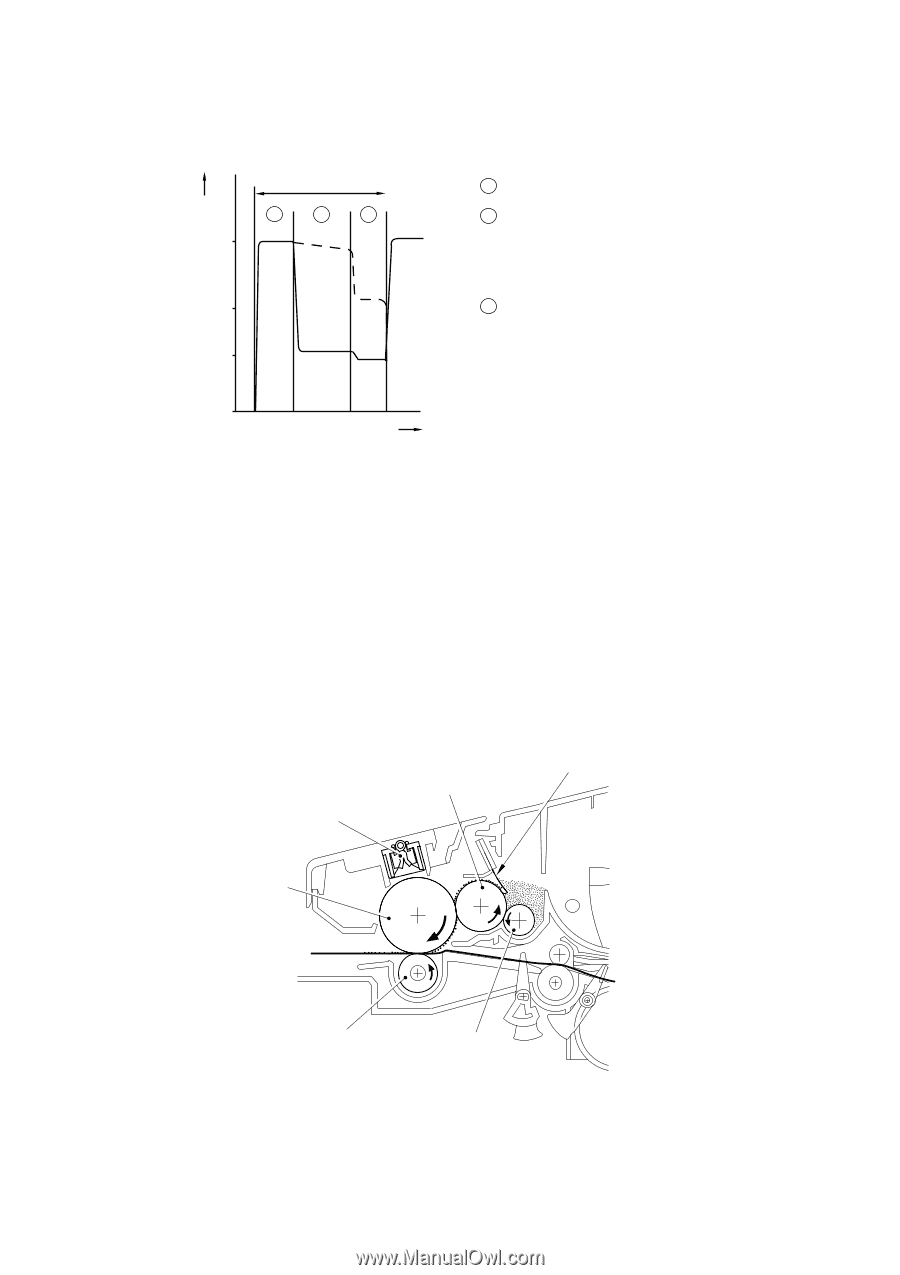
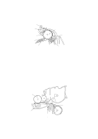
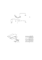
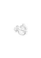
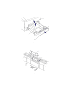
CHAPTER 3 THEORY OF OPERATION The area exposed to the laser beam is the image to be printed. The surface potential of the exposed area is reduced, forming the electrostatic image to be printed. Surface Potential (V) +870 1 Cycle of drum 1 2 3 (a) +420 (b) +200 1 Primary charging 2 Laser beam exposure and developing (a) Unexposed area ( Non image area ) (b) Exposed area ( Image area ) 3 Transfer the image to paper Drum Sleeve 0 Time Fig. 3-36 2.6.3 Developing Developing causes the toner to be attracted to the electrostatic image on the drum so as to transform it into a visible image. The developer consists of a non-magnetic toner. The development roller is made of conductive rubber and the supply roller (which is also made of conductive sponge) rotate against each other. The toner is charged and carried from the supply roller to the development roller. The toner adheres to the development roller and is conveyed to the photosensitive drum at an even thickness controlled by the blade. The toner is nipped between the development roller and the drum and developed onto the latent image on the drum. The electrostatic field between the drum and the development roller, which is DC-biased from the high-voltage power supply, creates the electrostatic potential to attract toner particles from the development roller to the latent image area on the drum surface. Blade Development roller Corona wire Photosensitive drum Transfer roller Supply roller Fig. 3-37 3-27
-
 1
1 -
2
-
3
-
4
-
5
-
6
-
7
-
8
-
9
-
10
-
11
-
12
-
13
-
14
-
15
-
16
-
17
-
18
-
19
-
20
-
21
-
22
-
23
-
24
-
25
-
26
-
27
-
28
-
29
-
30
-
31
-
32
-
33
-
34
-
35
-
36
-
37
-
38
-
39
-
40
-
41
-
42
-
43
-
44
-
45
-
46
-
47
-
48
-
49
-
50
-
51
-
52
-
53
-
54
-
55
-
56
-
57
-
58
-
59
-
60
-
61
-
62
-
63
-
 64
64 -
 65
65 -
 66
66 -
 67
67 -
 68
68 -
 69
69 -
 70
70 -
 71
71 -
 72
72 -
 73
73 -
 74
74 -
75
-
76
-
77
-
78
-
79
-
80
-
81
-
82
-
83
-
84
-
85
-
86
-
87
-
88
-
89
-
90
-
91
-
92
-
93
-
94
-
95
-
96
-
97
-
98
-
99
-
100
-
101
-
102
-
103
-
104
-
105
-
106
-
107
-
108
-
109
-
110
-
111
-
112
-
113
-
114
-
115
-
116
-
117
-
118
-
119
-
120
-
121
-
122
-
123
-
124
-
125
-
126
-
127
-
128
-
129
-
130
-
131
-
132
-
133
-
134
-
135
-
136
-
137
-
138
-
139
-
140
-
141
-
142
-
143
-
144
-
145
-
146
-
147
-
148
-
149
-
150
-
151
-
152
-
153
-
154
-
155
-
156
-
157
-
158
-
159
-
160
-
161
-
162
-
163
-
164
-
165
-
166
-
167
-
168
-
169
-
170
-
171
-
172
-
173
-
174
-
175
-
176
-
177
-
178
-
179
-
180
-
181
-
182
-
183
-
184
-
185
-
186
-
187
-
188
-
189
-
190
-
191
-
192
-
193
-
194
-
195
-
196
-
197
-
198
-
199
-
200
-
201
-
202
-
203
-
204
-
205
-
206
-
207
-
208
-
209
-
210
-
211
-
212
-
213
-
214
-
215
-
216
-
217
-
218
-
219
-
220
-
221
-
222
-
223
-
224
-
225
-
226
-
227
-
228
-
229
-
230
-
231
-
232
-
233
-
234
-
235
-
236
-
237
-
238
-
239
-
240
-
241
-
242
-
243
 |
 |