Brother International HL 1230 Service Manual - Page 70
Power Supply
 |
View all Brother International HL 1230 manuals
Add to My Manuals
Save this manual to your list of manuals |
Page 70 highlights
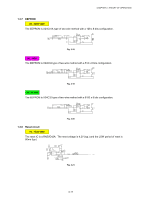
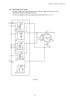
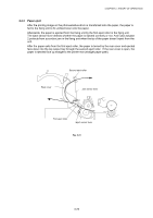
CHAPTER 3 THEORY OF OPERATION 1.6 Power Supply 1.6.1 Low-voltage power supply The power supply uses a switching regulation system to generate the regulated DC power (+5V and +24V), which are converted from the AC line. The regulated output and the production code of each power supply are listed below; Regulated Output Production Code +5V / 1.6 A +24V / 2.15 A 100V: MPW1555 200V: MPW1455 For the circuit diagram of the low-voltage power supply PCB, see Appendix 20 or 21. Fuse Lightning Surge Absorber Heater Circuit (Heater) Thermal Fuse Lamp Line Filter Fuse Rectifier Feedback Oscillator 24V Regulation Circuit 5V Regulation Circuit Fig. 3-25 3-20 (Engin Circuit) 24V 5V
-
 1
1 -
2
-
3
-
4
-
5
-
6
-
7
-
8
-
9
-
10
-
11
-
12
-
13
-
14
-
15
-
16
-
17
-
18
-
19
-
20
-
21
-
22
-
23
-
24
-
25
-
26
-
27
-
28
-
29
-
30
-
31
-
32
-
33
-
34
-
35
-
36
-
37
-
38
-
39
-
40
-
41
-
42
-
43
-
44
-
45
-
46
-
47
-
48
-
49
-
50
-
51
-
52
-
53
-
54
-
55
-
56
-
57
-
58
-
59
-
60
-
61
-
62
-
63
-
64
-
 65
65 -
 66
66 -
 67
67 -
 68
68 -
 69
69 -
 70
70 -
 71
71 -
 72
72 -
 73
73 -
 74
74 -
 75
75 -
76
-
77
-
78
-
79
-
80
-
81
-
82
-
83
-
84
-
85
-
86
-
87
-
88
-
89
-
90
-
91
-
92
-
93
-
94
-
95
-
96
-
97
-
98
-
99
-
100
-
101
-
102
-
103
-
104
-
105
-
106
-
107
-
108
-
109
-
110
-
111
-
112
-
113
-
114
-
115
-
116
-
117
-
118
-
119
-
120
-
121
-
122
-
123
-
124
-
125
-
126
-
127
-
128
-
129
-
130
-
131
-
132
-
133
-
134
-
135
-
136
-
137
-
138
-
139
-
140
-
141
-
142
-
143
-
144
-
145
-
146
-
147
-
148
-
149
-
150
-
151
-
152
-
153
-
154
-
155
-
156
-
157
-
158
-
159
-
160
-
161
-
162
-
163
-
164
-
165
-
166
-
167
-
168
-
169
-
170
-
171
-
172
-
173
-
174
-
175
-
176
-
177
-
178
-
179
-
180
-
181
-
182
-
183
-
184
-
185
-
186
-
187
-
188
-
189
-
190
-
191
-
192
-
193
-
194
-
195
-
196
-
197
-
198
-
199
-
200
-
201
-
202
-
203
-
204
-
205
-
206
-
207
-
208
-
209
-
210
-
211
-
212
-
213
-
214
-
215
-
216
-
217
-
218
-
219
-
220
-
221
-
222
-
223
-
224
-
225
-
226
-
227
-
228
-
229
-
230
-
231
-
232
-
233
-
234
-
235
-
236
-
237
-
238
-
239
-
240
-
241
-
242
-
243
-
244
-
245
-
246
-
247
-
248
-
249
-
250
 |
 |

CHAPTER 3
THEORY OF OPERATION
3-20
1.6
Power Supply
1.6.1
Low-voltage power supply
The power supply uses a switching regulation system to generate the regulated DC power
(+5V and +24V), which are converted from the AC line.
The regulated output and the production code of each power supply are listed below;
Regulated Output
Production Code
+5V / 1.6 A
+24V / 2.15 A
100V: MPW1555
200V: MPW1455
For the circuit diagram of the low-voltage power supply PCB, see
Appendix 20 or 21
.
Heater
Circuit
Thermal
Fuse
Lightning
Surge
Absorber
Feedback
Line
Filter
Fuse
Rectifier
Oscillator
24V
Regulation
Circuit
24V
5V
Lamp
(Heater)
(Engin Circuit)
Fuse
5V
Regulation
Circuit
Fig. 3-25