Brother International HL 1850 Service Manual - Page 147
gears.
 |
UPC - 012502603900
View all Brother International HL 1850 manuals
Add to My Manuals
Save this manual to your list of manuals |
Page 147 highlights
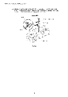
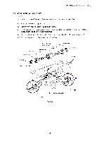
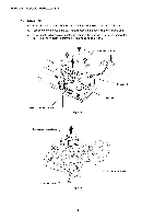
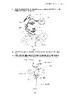
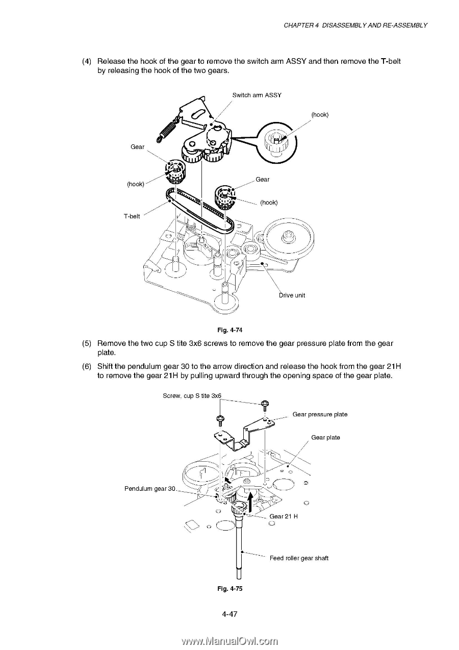
CHAPTER 4 DISASSEMBLY AND RE-ASSEMBLY (4) Release the hook of the gear to remove the switch arm ASSY and then remove the T-belt by releasing the hook of the two gears. Switch arm ASSY 0 ,..s (hook) Gear .,. d (hook) T-belt t N1 Gear (hook) ------___ V .(i ,,. 0 . rive unit Fig. 4-74 (5) Remove the two cup S tite 3x6 screws to remove the gear pressure plate from the gear plate. (6) Shift the pendulum gear 30 to the arrow direction and release the hook from the gear 21H to remove the gear 21H by pulling upward through the opening space of the gear plate. Screw, cup S tite 3x6 ....r _______-- Gear pressure plate 1.) Gear plate Pendulum gear 30 -----/ „--c-e-. L.,L.) c_D-- a CD 0 ,,t Gear 21 H e------- Feed roller gear shaft Fig. 4-75 4-47
-
 1
1 -
2
-
3
-
4
-
5
-
6
-
7
-
8
-
9
-
10
-
11
-
12
-
13
-
14
-
15
-
16
-
17
-
18
-
19
-
20
-
21
-
22
-
23
-
24
-
25
-
26
-
27
-
28
-
29
-
30
-
31
-
32
-
33
-
34
-
35
-
36
-
37
-
38
-
39
-
40
-
41
-
42
-
43
-
44
-
45
-
46
-
47
-
48
-
49
-
50
-
51
-
52
-
53
-
54
-
55
-
56
-
57
-
58
-
59
-
60
-
61
-
62
-
63
-
64
-
65
-
66
-
67
-
68
-
69
-
70
-
71
-
72
-
73
-
74
-
75
-
76
-
77
-
78
-
79
-
80
-
81
-
82
-
83
-
84
-
85
-
86
-
87
-
88
-
89
-
90
-
91
-
92
-
93
-
94
-
95
-
96
-
97
-
98
-
99
-
100
-
101
-
102
-
103
-
104
-
105
-
106
-
107
-
108
-
109
-
110
-
111
-
112
-
113
-
114
-
115
-
116
-
117
-
118
-
119
-
120
-
121
-
122
-
123
-
124
-
125
-
126
-
127
-
128
-
129
-
130
-
131
-
132
-
133
-
134
-
135
-
136
-
137
-
138
-
139
-
140
-
141
-
 142
142 -
 143
143 -
 144
144 -
 145
145 -
 146
146 -
 147
147 -
 148
148 -
 149
149 -
 150
150 -
 151
151 -
 152
152 -
153
-
154
-
155
-
156
-
157
-
158
-
159
-
160
-
161
-
162
-
163
-
164
-
165
-
166
-
167
-
168
-
169
-
170
-
171
-
172
-
173
-
174
-
175
-
176
-
177
-
178
-
179
-
180
-
181
-
182
-
183
-
184
-
185
-
186
-
187
-
188
-
189
-
190
-
191
-
192
-
193
-
194
-
195
-
196
-
197
-
198
-
199
-
200
-
201
-
202
-
203
-
204
-
205
-
206
-
207
-
208
-
209
-
210
-
211
-
212
-
213
-
214
-
215
-
216
-
217
-
218
-
219
-
220
-
221
-
222
-
223
-
224
-
225
-
226
-
227
-
228
-
229
-
230
-
231
-
232
-
233
-
234
-
235
-
236
-
237
-
238
-
239
-
240
-
241
-
242
-
243
-
244
-
245
-
246
-
247
-
248
-
249
-
250
-
251
-
252
-
253
-
254
-
255
-
256
-
257
-
258
-
259
-
260
-
261
-
262
-
263
-
264
-
265
-
266
-
267
-
268
-
269
-
270
-
271
-
272
-
273
-
274
-
275
-
276
-
277
 |
 |
CHAPTER
4
DISASSEMBLY
AND
RE
-ASSEMBLY
(4)
Release
the
hook
of
the
gear
to
remove
the
switch
arm
ASSY
and
then
remove
the
T
-belt
by
releasing
the
hook
of
the
two
gears.
Switch
arm
ASSY
Gear
(hook)
T
-belt
------___
V
0
,..s
.,.
.(i ,.
,
.
Gear
t
N1
0
(hook)
d
rive
unit
(hook)
Fig.
4-74
(5)
Remove
the
two
cup
S
tite
3x6
screws
to
remove
the
gear
pressure
plate
from
the
gear
plate.
(6)
Shift
the
pendulum
gear
30
to
the
arrow
direction
and
release
the
hook
from
the
gear
21H
to
remove
the
gear
21H
by
pulling
upward
through
the
opening
space
of
the
gear
plate.
Screw,
cup
S
tite
3x6
Gear
pressure
plate
....
r
_______--
Pendulum
gear
30
1.)
-----/
„----
ce.
a
CD
Gear
plate
L.,
L.)
c_D--
,,t
---
-------___
Gear
21
H
e-------
Feed
roller
gear
shaft
Fig.
4-75
0
4-47