Canon 1692B002 Service Manual
Canon 1692B002 Manual
 |
View all Canon 1692B002 manuals
Add to My Manuals
Save this manual to your list of manuals |
Canon 1692B002 manual content summary:
- Canon 1692B002 | Service Manual - Page 1
Service Manual iPF8000 series iPF8000 Oct 3 2006 - Canon 1692B002 | Service Manual - Page 2
- Canon 1692B002 | Service Manual - Page 3
release technical information as the need arises. In the event of major changes in the contents of this manual over a long or short period, Canon will issue a new edition of this manual. The following paragraph does not apply to any countries where such provisions are inconsistent with local law - Canon 1692B002 | Service Manual - Page 4
(fire). Indicates an item prohibiting disassembly to avoid electric shocks or problems. Indicates an item requiring disconnection of the power plug from the electric in question. REF. Provides a description of a service mode. Provides a description of the nature of an error indication. Introduction - Canon 1692B002 | Service Manual - Page 5
unit door, which results in supplying the machine with power. 2. In the digital circuits, '1'is used to indicate that the voltage level of a given signal controller PCB to the loads. The descriptions in this Service Manual are subject to change without notice for product improvement or other purposes - Canon 1692B002 | Service Manual - Page 6
- Canon 1692B002 | Service Manual - Page 7
Precautions...1- 18 1.7.2.1 Printhead...1- 18 1.7.2.2 Ink tank ...1- 19 1.7.2.3 Handling the Printer ...1- 20 1.7.3 Precautions When Servicing Printer...1- 21 1.7.3.1 Notes on the Data Stored in the Printer ...1- 21 1.7.3.2 Confirming the Firmware Version ...1- 21 1.7.3.3 Precautions Against Static - Canon 1692B002 | Service Manual - Page 8
14 2.3.3.2 Paper Path ...2- 16 2.3.3.3 Cutter Unit...2- 16 2.4 Printer Electrical System ...2- 16 2.4.1 Outline...2- 16 2.4.1.1 Overview ...2- 16 2.4.2 PCB...2- 19 2.4.4.1 Head relay PCB components...2- 19 2.4.5 Motor Driver ...2- 19 2.4.5.1 Media take-up unit components...2- 19 2.4.6 Maintenance - Canon 1692B002 | Service Manual - Page 9
feed paper more...6- 2 6.1.2.7 Paper Type Wrong...6- 2 6.1.2.8 GARO W12xx ...6- 2 6.1.2.9 Check printed document...6- 2 6.1.2.10 Prepare for parts replacement. Call for service...6- 2 6.1.2.11 Parts replacement time has passed. Call for service...6- 3 6.1.3 Troubleshooting When Errors Occur ...6- 3 - Canon 1692B002 | Service Manual - Page 10
be written...6- 11 6.1.3.44 03900001-4042/03900001-4049 Firmware error ...6- 11 6.1.3.45 E194-4034 Sensor calibration error ...6- 11 6.1.4 Troubleshooting When Service Call Errors Occur 6- 12 6.1.4.1 E141-4046 Recovery system's count error ...6- 12 6.1.4.2 E144-4047 Supply system's count error - Canon 1692B002 | Service Manual - Page 11
Up ...6- 37 6.3.1 Firmware Update Tool ...6- 37 6.4 Service Tools ...6- 38 6.4.1 List of Tools ...6- 38 Chapter 7 SERVICE MODE 7.1 Service Mode...7- 1 7.1.1 Service Mode...7- 1 7.1.2 Map of the Service mode...7- 1 7.1.3 Details for Service mode ...7- 6 7.2 Special Mode ...7- 12 7.2.1 Special Modes - Canon 1692B002 | Service Manual - Page 12
Contents - Canon 1692B002 | Service Manual - Page 13
Chapter 1 PRODUCT DESCRIPTION - Canon 1692B002 | Service Manual - Page 14
- Canon 1692B002 | Service Manual - Page 15
Other Precautions...1-18 1.7.2.1 Printhead ...1-18 1.7.2.2 Ink tank...1-19 1.7.2.3 Handling the Printer ...1-20 1.7.3 Precautions When Servicing Printer ...1-21 1.7.3.1 Notes on the Data Stored in the Printer...1-21 1.7.3.2 Confirming the Firmware Version ...1-21 1.7.3.3 Precautions Against Static - Canon 1692B002 | Service Manual - Page 16
- Canon 1692B002 | Service Manual - Page 17
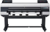
photographic picture quality. This printer is a stand-mounted type printer and is capable of output (R) [3] Ink tank cover unit (L) [4] Operation panel [5] Stand (USA: Bundled/ Others: Option) [6] Basket [7] Media take-up unit ( Media take-up unit (option) is supported. - Media take-up unit (option) - Canon 1692B002 | Service Manual - Page 18
F-1-4 1.2.5 Roll holder 0013-6371 The printer comes with a roll holder for paper tubes having an inside diameter of 2 inches as standard. It supports an optional roller holder for paper tubes a weight roller. Rolls may also be manually taken up by using a button on the media take-up unit. 1-2 - Canon 1692B002 | Service Manual - Page 19
of the media take-up unit include: - An adapter may be installed to support a 3-inch paper tube. - Rolls can be rewound by feeding them backward to Type Feeding system Feeding capacity Delivery method Bubblejet printer (stand model) Roll media: Manual (front loading) Cut media: Paper tray (front - Canon 1692B002 | Service Manual - Page 20
,Japanese Paper Washi, Colored Coated Paper, CAD Tracing Paper,CAD Translucent Matte Film,CAD Clear Film Supported thickness 0.07 mm to 0.8 mm Media size (Roll media) Width: 254 mm (10") off: 1W or less Printer unit dimensions (WxDxH) 1893 mm x 975 mm x 1144 mm (including stand and basket) - Canon 1692B002 | Service Manual - Page 21
High CAD Tracing Paper CAD Translucent Matte Film CAD Clear Film Line drawing /Text draft standard High *1 Uni-directional can be selected optionally from the printer driver. Processing resolution (dpi) 300 300 600 600 600 600 300 600 600 600 600 600 300 600 600 600 600 Print resolution (dpi - Canon 1692B002 | Service Manual - Page 22
Delivery support [5] Ink tank cover [6] Operation panel [7] Release lever [8] Stand [9] Basket [10] Media take-up unit [7] [9] [10] [8] F-1-9 T-1-3 Open this cover to install a printhead, load media or clear jammed paper inside the printer. Allow printed paper to be delivered. Open these guides - Canon 1692B002 | Service Manual - Page 23
an expansion PCB on this slot. Connect the Ethernet cable to this connector. Connect the USB cable to this port. Holds printer manuals, assembly tools, and other items. Connect the power cord to this connector. [1] [2] [4] [5] [3] Chapter 1 0014-8838 0012-6263 [1] Carriage cover [2] Printhead - Canon 1692B002 | Service Manual - Page 24
or the previous item/ setting. Offline: This button functions as a manual feed button and feeds the media. Menu : This button functions as off the printer. When the media is not loaded: Displays the instructions of loading the media. When the media is loaded: Displays the instructions of removing - Canon 1692B002 | Service Manual - Page 25
no print job. On:This indicates that a warning message is displayed. Flashing:This indicates that an error message is displayed. Off:This indicates that the printer is normal or the power is turned off. On:This indicates that the or roll media is selected as the paper source. Off:This indicates - Canon 1692B002 | Service Manual - Page 26
"Chk Remain.Roll" ### m / ### feet Cut Sheet Type (Media Type) Paper Details (Media Type) --->See Paper Details Menu Adjust Printer --->See Adjust Printer Menu Interface Setup --->See Interface Setup Menu Maintenance Repl.Maint.C No Yes Replace P.head Printhead L No Yes Printhead - Canon 1692B002 | Service Manual - Page 27
) Weak Width Detection Off On NearEnd RllMrgn 5mm 20mm Cut Speed Standard Fast Slow Trim Edge First Forced Automatic No Cutting Cutting Mode Automatic Eject Manual Bordless Margin Automatic Fixed CutDustReduct. Off On Nr End Sht Mrgn 5mm 20mm Return Defaults No Yes F-1-16 Chapter 1 1-11 - Canon 1692B002 | Service Manual - Page 28
Chapter 1 Adjust Printer Menu Adjust Printer Auto Head Adj. Standard Adj. No Yes Advanced Adj. No Yes Auto Print Off On Manual Head Adj No Yes Auto Band Adj. Standard Adj. No Yes Advanced Adj. No Yes Manual Band Adj No Yes Adjust Length No Yes F-1-17 1-12 - Canon 1692B002 | Service Manual - Page 29
. 2 min. 5min.10min. 30 min.) 60 min. TCP/IP TCP/IP On IP Mode Automatic Manual Protocol DHCP On Off BOOTP On Off RARP On Off IP Setting IP Address ( 0-255. 0-255. 802.3 Ethernet SNAP Print Service Bindery PServer RPrinter NDSPserver NPrinter AppleTalk On Off Ethernet Driver Auto Detect On Off Comm - Canon 1692B002 | Service Manual - Page 30
Chapter 1 System Setup Menu (1/2) System Setup Warning Buzzer Off On Ignore Mismatch Off On Skip Take-Up Err Off On Keep Media Size Off On *Displays only when media take-up unit is installed Paper Size Basis Sht Selection 1 ISO A3+ ANSI B Super Sht Selection 2 ISO B1 ANSI F Roll Selection 1 ISO - Canon 1692B002 | Service Manual - Page 31
System Setup Menu (2/2) (System Setup) Chapter 1 Time Zone --->See Time Zone Menu Date Format yyyy/mm/dd dd/mm/yyyy mm/dd/yyyy Date & Time Date(yyyy/mm/dd) Time(hh:mm) Language English Contrast Adj. -4 (0) +4 Reset PaprSetngs No Yes *Returnes settings of "Paper details" to the state of - Canon 1692B002 | Service Manual - Page 32
and flexible cable; feed motor-driven feed roller and pinch roller; and purge motor-driven purge unit. To prevent accidents, the upper cover of the printer is locked during printing so that itdoes not open. If the upper cover is opened in the online/offline mode, the carriage motor, feed motor - Canon 1692B002 | Service Manual - Page 33
[12] Media take-up unit 0014-0264 1. Ink passages Be careful not to touch the ink passages of the printer or to allow ink to stain the workbench, hands, clothes or the printer under repair. The ink flows through the ink tank unit, carriage unit, purge unit, maintenance-jet tray, borderless print - Canon 1692B002 | Service Manual - Page 34
unit, main rail unit, external unit, or purge unit. These stains may soil the print media or hands and clothes when servicing the printer, wipe them off carefully with a soft, well-wrung damp cloth. [2] [1] [3] F-1-26 T-1-11 [1] Purge unit [2] Upper cover [3] Platen unit/Carriage unit/Main - Canon 1692B002 | Service Manual - Page 35
foreign matter from entering the ink port, installed the unpacked ink tank in the printer immediately. 2. Handling the Ink Tank To prevent foreign matter from entering the ink flow path and causing ink suction and printing problems, never touch the ink port and contacts of the ink tank. When you - Canon 1692B002 | Service Manual - Page 36
printing, the carriage is mechanically locked by the lock arm in the purge unit at the same moment the printhead is capped. Before transporting the printer, secure the carriage at its home position using belt stoppers[1] so that the carriage does not become separated from the lock arm and damage or - Canon 1692B002 | Service Manual - Page 37
When Servicing Printer 1.7.3.1 Notes on the Data Stored in the Printer 0013-5942 This printer counts to up update the main controller, refer to TROUBLESHOOTING > Version Up. 1.7.3.3 Precautions Against Static 5950 The printer has a diagnostic feature which analyzes printer problems (which may - Canon 1692B002 | Service Manual - Page 38
Chapter 1 1-22 - Canon 1692B002 | Service Manual - Page 39
Chapter 2 TECHNICAL REFERENCE - Canon 1692B002 | Service Manual - Page 40
- Canon 1692B002 | Service Manual - Page 41
Unit...2-16 2.3.3.3.1 Structure of the cutter unit...2-16 2.4 Printer Electrical System...2-16 2.4.1 Outline...2-16 2.4.1.1 Overview ...2-16 2.4.2 Relay PCB ...2-19 2.4.4.1 Head relay PCB components ...2-19 2.4.5 Motor Driver ...2-19 2.4.5.1 Media take-up unit components ...2-19 2.4.6 Maintenance - Canon 1692B002 | Service Manual - Page 42
Contents 2.4.7 Power Supply ...2-20 2.4.7.1 Power supply block diagram...2-20 2.5 Detection Functions with Sensors ...2-20 2.5.1 Cover system...2-20 2.5.2 Ink passage system...2-21 2.5.3 Carriage system...2-23 2.5.4 Paper path system ...2-24 2.5.5 Humidity sensor ...2-24 2.5.6 Media take-up Unit - Canon 1692B002 | Service Manual - Page 43
PCB in order to discharge ink from the nozzles. On a printhead, six arrays of nozzles are provided in six arrays in a staggered pattern. This printer uses a pair of printheads. (The Y, PC, C, PGy, Gy, MBk, PM, M, Bk, R, G, B nozzles are mounted in this order from the left.) Even-numbered nozzle data - Canon 1692B002 | Service Manual - Page 44
sequence as shown below. If the power cord is disconnected from the wall outlet or the upper cover or any other cover is opend, the printer cancels the ongoing operation and shuts down immediately. Since printhead capping may or may not have been carried out properly, reconnect the power cord to - Canon 1692B002 | Service Manual - Page 45
the print quality requirement for a print mode, uneven density problems caused by variations in the rate of discharge among different passes per band (equivalent of the length of a nozzle). Configure the print driver for print quality setting Standard to enable standard mode. c) High quality mode - Canon 1692B002 | Service Manual - Page 46
attached to the lower left part of the carriage, and manual adjustment, in which print position adjustment patterns that are slightly driver. This feature is particularly useful on paper that takes time to dry after printing, such as films. 2.2.8 White Raster Skip 0012-6322 This printer supports - Canon 1692B002 | Service Manual - Page 47
ink passage comprises ink tanks, a printheads, caps, a maintenance jet tray, a maintenance cartridge, ink tubes interconnecting the mechanical components of the printer, and a suction pump that is driven to suck inks. It supplies, circulates, sucks and otherwise handles inks. The ink passage (per - Canon 1692B002 | Service Manual - Page 48
the dot count reaches a predesigned value in this state, an ink out condition is assumed. b) Ink port Depressing the ink tank fixer lever on the printer would cause would cause a hollow needle to pierce the ink tank port sealed by a rubber plug, linking the ink passage of the ink to the - Canon 1692B002 | Service Manual - Page 49
Chapter 2 [4] [3] [1] [5] [2] [5] F-2-6 T-2-2 [1] Ink tank [2] EEPROM [3] Ink port [4] Air passage [5] Notch for preventing incorrect installation e) Subtank The subtank installed under each ink tank complements the work of the ink tank, agitating the ink in the tank. If the ink tank runs - Canon 1692B002 | Service Manual - Page 50
varied as a result of differing paper thicknesses, cockled or curled paper or other problems, the printer is liable to mist generation as the carriage height increases or to head rubbing as an ink tube, which runs between the tube guides via joints to reach the carriage and follows up is motion. 2-8 - Canon 1692B002 | Service Manual - Page 51
the motion of the carriage together with the tube guide. A photocoupler encoder mounted in the lower part HP sensor on the right side of the printer. When the linear scale position is set as a of light reflected upon the white plate. (Service mode: SERVICE MODE>ADJUST>GAP CALIB) h) Rail cleaner - Canon 1692B002 | Service Manual - Page 52
Chapter 2 [1] [2] [3] [10] [7] [6] [4] [5] [12] [9] [8] [11] F-2-9 T-2-6 2.3.2.4 Printhead [1] Carriage relay PCB [2] Multi sensor [3] Head relay PCB [4] Lift cam sensor [5] Sensor flag [6] Lift cam [7] Shaft cleaner [8] Maintenance jet tray [9] Carriage HP sensor [10] Multisensor - Canon 1692B002 | Service Manual - Page 53
the printhead to protect from drying and foreign matter adherence. Capping takes place at the end of printing, during a suction operation and when the printer stands by in the wake of an error occurrence. The capping function connects the printhead to the ink passage of the purge unit. b) Cleaning - Canon 1692B002 | Service Manual - Page 54
count On execution of the menu action [Head Cleaning] Manual cleaning (Head cleaning A) Manual cleaning (Head cleaning B) Cleaning 1 (Normal cleaning) adjustment) On execution of Move After execution of Move Printer from the menu Printer from the menu After Power-on at secondary installation - Canon 1692B002 | Service Manual - Page 55
by the wiper blades moving at a constant speed to the front of the printer after the end of a print or suction operation. A wiper blade set perpendicularly to or replacement required indication (service call error) is issued. T-2-9 Display Replacement warning indication Service calls Times 71,250 - Canon 1692B002 | Service Manual - Page 56
floating during printing or springing back from the paper are collected in the mist fan unit by air flow in the printer. Two mist fans located on the rear side of the printer makes the airflow that carries the ink mists to the mist fan unit. 0014-8865 F-2-15 2.3.3 Paper Path 2.3.3.1 Outline - Canon 1692B002 | Service Manual - Page 57
sensor 2) Multi sensor light quantity adjustment 3) Paper width detection sensor 4) Paper leading edge detection sensor 5) Paper skew detection sensor Memo: Press the [ ] key while the printer is offline to deliver paper, the [ ] key to rewind the paper. Chapter 2 2-15 - Canon 1692B002 | Service Manual - Page 58
the carriage cuts roll media automatically. Cutter unit won't cut roll media if the print driver is configured otherwise. 2.4 Printer Electrical System 2.4.1 Outline 2.4.1.1 Overview 0014-8871 The printer electrical system consists of the main controller PCB and power supply PCB which are mounted - Canon 1692B002 | Service Manual - Page 59
a) ASIC(IC1,IC2) The ASIC(IC1/IC2) with a 32/16-bit internal bus is driven in sync with the 132/66 MHz external clock. It supports the following functions: Image processing unit This unit converts the RGB multi-bit image data or CMYK multi-bit data received from the host computer - Canon 1692B002 | Service Manual - Page 60
motor(R) control signals based on the control signal from the ASIC. e) Driver IC (IC3900) This IC generates valve motor(L) control signals based on the related to the user/servicing. MEMO: After replacement of the main controller PCB, the printer must be started up in the service mode to take over - Canon 1692B002 | Service Manual - Page 61
PCB to the printhead. The function for processing image data is not supported. b) Sensor relay function This function relays the input signals from the to the main controller PCB. 2.4.5 Motor Driver 2.4.5.1 Media take-up unit components 0014-2480 IC104 a) Driver IC (IC104) F-2-21 Media take-up - Canon 1692B002 | Service Manual - Page 62
/closed states of the upper cover. When the upper cover close, the switches are pressed to detect the closed state of the upper cover. The printer has one switch installed on the left and right sides each to prevent one-sided closure of the upper cover. Ink tank cover switches (L) / (R) The - Canon 1692B002 | Service Manual - Page 63
Chapter 2 Ink tank cover switch Pressure release switch Upper cover lock switch F-2-24 2.5.2 Ink passage system 0012-6492 Agitation cam sensor Valve open/closed detection sensor Pump cam sensor Head management sensor Pump encoder F-2-25 Pump cam sensor As the cam rotates, it shields the - Canon 1692B002 | Service Manual - Page 64
Chapter 2 Rotary flag Sensor - Carriage lock - Capping - Suction - Air passage valve open - Idle suction - Printing - Suction during printing - Wiping - Carriage lock - Air passage - Carriage move - Maintenance jet - Idle suction F-2-26 Pump encoder The photointerrupter-based sensor reads - Canon 1692B002 | Service Manual - Page 65
the ambient temperature to which the carriage is exposed. The resistance of the thermistor that varies as a function of temperature changes in the printer is transmitted to the main controller via the carriage relay PCB. The ambient temperature is used to help calibrate the head temperature sensor - Canon 1692B002 | Service Manual - Page 66
paper. Feed roller HP sensor The feed roller HP sensor detects transitions from white (transmitted), or a reference, to black (shielded) when the printer is switched on, thereby setting the home position of feed roller eccentricity correction. Feed roller encoder The feed roller encoder is driven to - Canon 1692B002 | Service Manual - Page 67
Chapter 2 Humidity sensor The humidity sensor detects the temperature and relative humidity around the printer to implement head height adjustment, maintenance jet control, waste ink evaporation calculation and suction fan control on the basis of the temperature and relative humidity - Canon 1692B002 | Service Manual - Page 68
- Canon 1692B002 | Service Manual - Page 69
Chapter 3 INSTALLATION - Canon 1692B002 | Service Manual - Page 70
- Canon 1692B002 | Service Manual - Page 71
Pre-Checks...3-1 3.1.2 Unpacking and Installation ...3-1 3.1.2.1 Checking the Contents ...3-1 3.1.2.2 Assembling the Stand...3-3 3.1.2.3 Installing the Printer ...3-6 3.1.2.4 Installing the Basket ...3-7 3.1.2.5 Installing the Media Take-Up Unit (Option) ...3-11 3.1.2.6 Removing Protection Materials - Canon 1692B002 | Service Manual - Page 72
- Canon 1692B002 | Service Manual - Page 73
Making Pre-Checks 3.1.1.1 Making Pre-Checks Follow the instructions in the included "Quick Start Guide" when installing the product. Refer to the package .3") 200mm (7.9") F-3-2 3.1.2 Unpacking and Installation 3.1.2.1 Checking the Contents 0014-8918 1) Check for the components. a) Printer 3-1 - Canon 1692B002 | Service Manual - Page 74
Chapter 3 6 5 7 3 5 4 1 2 1 Printer 3 Power cord 5 Ink tanks (12 colors) 7 Hex wrench b) Stand and basket 1 5 F-3-3 T-3-2 2 4 6 Roll holder Printheads (2pcs.) Eject supports (4pcs.) 3 2 4 8 7 9 12 15 13 6 10 11 14 1 Basket unit 3 Bottom stand stay 5 Right stand leg 7 Rod - Canon 1692B002 | Service Manual - Page 75
9 Basket arm R 11 Rod holder adapter (2pcs.) 13 Spanner 15 M4 hex screws (20pcs.) c) Media take-up unit (option) 2 4 1 10 Leg cover (2pcs.) 12 M8 hex bolts (8pcs.) 14 Hex wrench 3 11 10 6 12 5 8 9 7 Chapter 3 F-3-5 T-3-4 1 Weight flange 1 / 2 (2pcs. each) 2 Media take-up unit L 3 - Canon 1692B002 | Service Manual - Page 76
. F-3-8 Rotate both ends of the stand simultaneously when standing the stand upright. Rotating only one side before the other may bend the stand and cause problems in assembly. 4) Insert the left end of the top stand stay into the side hole [1] on the left stand leg, and insert the right end - Canon 1692B002 | Service Manual - Page 77
[1] [2] F-3-9 MEMO: Insert the left end of the top stand stay first. The right end can only be pushed into a restricted position. 5) Secure the top stand stay to the left and right stand legs using the four M8 hex bolts on each side. Chapter 3 [1] [1] F-3-10 6) Attach the leg cover to the left - Canon 1692B002 | Service Manual - Page 78
more than four people. 1) Remove the black belts from around the printer and remove the top packaging material. F-3-13 2) While two people are holding the carrying handles under the printer on one end and lifting the printer a little, have a third person to remove the packaging material from under - Canon 1692B002 | Service Manual - Page 79
positions is dangerous and may cause injury and damage if the printer is dropped. 4) Align the triangles on the back of the printer and the stand when setting the printer on the stand. Secure the printer and the stand firmly together using four M4 hex screws on each side. F-3-17 3.1.2.4 Installing - Canon 1692B002 | Service Manual - Page 80
Chapter 3 [2] [1] [3] [4] F-3-18 2) Insert the left side of the middle basket rod to the basket arm L [1] [A], than push in the arm fully into the hole on the left side of the bottom stand stay [B]. Secure the basket arm L [1] and R [2] using one M4 hex screw on each side [C]. [1] 3) Attach the - Canon 1692B002 | Service Manual - Page 81
Chapter 3 F-3-21 5) Spread out the basket unit with white tag [1] of the basket cloth at the front on the right side and the black cord [2] at the back. [2] [1] F-3-22 6) Insert the basket rod (in the middle of the basket cloth) in the hole [1] on the bottom of the rod holder, and thread the black - Canon 1692B002 | Service Manual - Page 82
Chapter 3 [2] [1] F-3-23 7) Pull out the basket cloth with the edge facing out. Bringing the edge of the basket cloth inside may prevent paper ejection. F-3-24 8) Attach the basket rod (at the front of the basket unit) to the tips [1] of the basket arm L and R. 3-10 - Canon 1692B002 | Service Manual - Page 83
Chapter 3 [1] F-3-25 9) Pull the basket rod [1] (at the front of the basket unit) all the way out and lift the rod to lock the rod in place. [1] F-3-26 3.1.2.5 Installing the Media Take-Up Unit (Option) 0014-8925 Install the media take-up unit (option) 1) In case the basket is installed, lift the - Canon 1692B002 | Service Manual - Page 84
Chapter 3 [1] F-3-27 2) Firmly secure the left and right media take-up unit mounting brackets to the front [1] and the back [2] of the top stand stay using four M4 hex screws on each side. 3-12 - Canon 1692B002 | Service Manual - Page 85
Chapter 3 [1] [2] F-3-28 3) Hook up the hole [1] of the left media take-up unit with the protrusion [2] of the left media take-up unit mounting bracket, and hook up the hole [3] of the right media take-up unit with the protrusion [4] on the right media take-up unit mounting bracket. Secure the media - Canon 1692B002 | Service Manual - Page 86
Chapter 3 [2] [1] [3] [4] [5] [5] F-3-29 4) Place the media take-up sensor unit under the bottom stand stay, than pull up the cord of the media take-up sensor unit through the hole of the right stand leg. F-3-30 5) With the media take-up sensor unit against the underside of the bottom stand - Canon 1692B002 | Service Manual - Page 87
Chapter 3 [1] [2] [2] [1] [1] F-3-31 Arrange the basket cloth and basket rod so they do not interfere with the media take-up sensor (indicated by the dotted line). F-3-32 6) Plug the cord of the media take-up sensor unit into the right media take-up unit. 3-15 - Canon 1692B002 | Service Manual - Page 88
power cord of the right media take-up unit to the back of the printer and pass the cord through the cord holders. After passing the cord behind holders, plug the cord into the power supply connector on the back of the printer. [1] F-3-34 When plugging in the power cord, be careful about the positions - Canon 1692B002 | Service Manual - Page 89
Chapter 3 OFF ON [2] [1] F-3-35 3.1.2.6 Removing Protection Materials 0014-8930 1) Remove the tape and other packaging material used to secure the printer. 2) Open the upper cover. F-3-36 F-3-37 3) Lift the release lever [1] [A], remove the protective sheet [2] from the platen, and lower the - Canon 1692B002 | Service Manual - Page 90
have been removed since these are needed when moving the printer to another location later. Neglecting to attach the belt stopper may cause damage to the printer when moving the printer to another location. 5) Lift the ejection guide. 6) Attach four eject supports [1] on the back of the ejection - Canon 1692B002 | Service Manual - Page 91
the ejection guide and the upper cover. [1] F-3-41 3.1.3 Checking the Images/Operations F-3-42 3.1.3.1 Checking the Image and Operation 0014-1896 Turn on the printer. Load the print heads, ink tanks, and media following the instructions shown on the operation panel. Install the printer driver in - Canon 1692B002 | Service Manual - Page 92
- Canon 1692B002 | Service Manual - Page 93
Chapter 4 DISASSEMBLY/REASSEMBLY - Canon 1692B002 | Service Manual - Page 94
- Canon 1692B002 | Service Manual - Page 95
Contents 4.1 Service Parts...4-1 4.1.1 Service parts...4-1 4.2 Disassembly/Reassembly...4-1 4.2.1 Diassembly/Reassembly ...4-1 4.3 Points to Note on Disassembly and Reassembly ...4-4 4.3.1 Note on locations prohibited from disassembly...4-4 4.3.2 Moving the carriage manually ...4-4 4.3.3 Units - Canon 1692B002 | Service Manual - Page 96
- Canon 1692B002 | Service Manual - Page 97
, be careful that the roller is not scratched or marked during storage or transport of the service parts, when removing them from the individual boxes, when assembling, or performing any other operations and assembly flows * Ink drainage in a dotted line performs manual or automatic either. 4-1 - Canon 1692B002 | Service Manual - Page 98
Carriage Unit Disassembly Flow c: Connector h: Hook s: Screw Printer Automatic ink drain Left/right circle cover (L) (h1) Left/right tank units (s4) Upper rear cover (s5) Upper cover Manual ink drain Head management sensor (s1) Pulley base (s3) Lift unit (s5) Cutter unit Carriage - Canon 1692B002 | Service Manual - Page 99
/right ink tank units (s4) Upper rear cover (s5) Upper cover Manual ink drain Move the carriage to above the platen Left/right printhead Left F-4-3 3. Purge Unit Disassembly Flow c: Connector h: Hook s: Screw Printer Right circle cover (L) (h1) Right circle cover (S) (h1) Right side covers - Canon 1692B002 | Service Manual - Page 100
Ink Tank unit Disassembly Flow c: Connector h: Hook s: Screw Printer Right circle cover (L) (h1) Right circle cover (S) (h1) Right side covers (s3, h2) Left/right tank cover units (s3) Move the carriage to above the platen Manual ink drain Drain the ink in subtanks Remove the left/right - Canon 1692B002 | Service Manual - Page 101
Chapter 4 [1] F-4-7 4.3.3 Units requiring draining of ink 0014-8953 When disassembling the following units of the ink passage, drain the filled ink completely to prevent ink leakage. For how to drain the ink, refer to DISASSEMBLY/REASSEMBLY > Points to Notes on Disassembly and Reassembly > Draining - Canon 1692B002 | Service Manual - Page 102
Chapter 4 [3] [1] b) Left circle cover (S)/Right circle cover (S) Removing the left circle cover (S)/right circle cover (S) 1) Remove circle cover (S) [1] by turning it forward to remove the hook [2] F-4-9 [1] F-4-10 Installing left circle cover (S)/right circle cover (S) 1) Install circle - Canon 1692B002 | Service Manual - Page 103
[1] [3] [2] F-4-12 d) Operation panel Removing the operation panel 1) To remove the operation panel[1], remove hook [2] with a flathead screwdriver and remove two connectors [3]. Chapter 4 [3] [2] [1] F-4-13 e) Upper left cover/upper right cover Removing the upper left cover/upper right cover 1) - Canon 1692B002 | Service Manual - Page 104
Chapter 4 [1] [2] F-4-14 f) Right front cover Removing the right front cover 1) To remove right front cover [1], remove right circle cover (L), right circle cover (S), right side covers, upper right cover the operation panel. 2) Remove two screws [2]. [2] [1] F-4-15 g) Rear cover, right/ rear - Canon 1692B002 | Service Manual - Page 105
cover and left/ right ink tank cover unit. 2) Remove two screws [1]. 3) Remove screw [2] from the support plate at inner side of the printer. 4) Remove screw [4] from the support plate [3] at outer side of the printer, loosen screw [5] and slide the support plate to open the ink tank unit. 4-9 - Canon 1692B002 | Service Manual - Page 106
left , and left/ right ink tank cover units and then open the left/ right ink tanks. 2) Remove two screws [1] on front side of the printer and three screws [2] on the rear side, and then remove upper rear cover [3]. [1] [3] [1] [2] Note on installing the upper rear cover 1) Fit three rear-panel - Canon 1692B002 | Service Manual - Page 107
Chapter 4 [1] [2] [2] [1] [2] F-4-22 m) Release lever Removing the release lever 1) To remove release lever [1], remove the purge unit and then remove the release lever. To do so, keep pinch roller [2] pressurized to ease to work of phase alignment during gear installation. Reinstalling the - Canon 1692B002 | Service Manual - Page 108
replacing the feed roller HP sensor, feed roller encoder and feed roller This printer as shipped has the feed roller eccentricity (that is, variations in the rate adjustment. Execute service mode under the following conditions to launch automatic adjustment: Service mode: SERVICE MODE > ADJUST - Canon 1692B002 | Service Manual - Page 109
4) Release the ink tube from the guide, detach four link levers [1] from the printhead fixer lever, than remove two joint bases [2]. [1] Chapter 4 [2] 5) Remove two screws [1] and ink tube cover [2]. F-4-26 [1] [2] 6) Detach joints [1] - Canon 1692B002 | Service Manual - Page 110
or when removing the joint base from the carriage. [1] F-4-30 10) Twist off belt fixer knob [1] to loosen the belt, and remove spring [2], guide [3] and pulley[4]. [3] [2] [1] [4] F-4-31 11) Release carriage belt from the pulley of the carriage motor. 12) Remove two screws [1] and pulley base - Canon 1692B002 | Service Manual - Page 111
cutter unit, and lay the caterpillar of the ink tube unit on its side, and then remove the carriage from the right side of the printer. - To remove the carriage unit, pull it out of position keeping the carriage unit level with care not to harm the linear scale. Flaws on - Canon 1692B002 | Service Manual - Page 112
varied from one unit to another, the printer has its optical axis corrected and paper Service mode: SERVICE MODE > ADJUST > GAP CALIB 3) Sensor correction for calibration - Service mode: SERVICE cable leading to the carriage PCB cover from the guide. 5) Remove three screws [1] and release ink tube - Canon 1692B002 | Service Manual - Page 113
roller encoder, or feed roller related to correction of feed roller eccentricity, adjustment is required. Use the service mode under the following conditions: Service mode: SERVICE MODE > ADJUST > PRINT PATTERN > LF TUNING Media type: Glossy photo paper 4.3.9 Purge unit 0014-8978 a) Removing the - Canon 1692B002 | Service Manual - Page 114
Chapter 4 [2] [3] [1] F-4-40 2) Remove connector [1] and three screws [2] and then remove purge unit [3]. [1] [2] [3] F-4-41 4.3.10 Ink tank unit 0014-8979 a) Removing ink tank units 1) Drain the ink. See Disassembly/Reassembly > Points to Note on Disassembly/Reassembly >Draining the ink. 2) - Canon 1692B002 | Service Manual - Page 115
unit at screw position [2]. Install the left ink tank unit at screw position [3]. (Installing position of each ink tank units are inner side of the printer.) 4-19 - Canon 1692B002 | Service Manual - Page 116
Chapter 4 [3] [2] [1] [3] [2] F-4-44 c) Removing the valve motor unit 1) To remove the valve motor unit, remove the ink tank cover unit. 2) Remove three screws [1], two connectors [2] and bearing [3], and then remove valve motor unit [4]. 4-20 - Canon 1692B002 | Service Manual - Page 117
Chapter 4 [2] [1] [1] [4] [3] F-4-45 4.3.11 Linear encoder 0014-8985 a) Removing the linear encoder 1) Move the carriage to above the platen. 2) Remove two screws [1] and upper rear stay [2]. [1] [2] [1] 3) Remove two screws [1] and linear encoder [2]. F-4-46 4-21 - Canon 1692B002 | Service Manual - Page 118
carriage unit is varied from one unit to another, the printer has its optical axis corrected to adjust the non-discharging nozzle When the main controller PCB and maintenance cartridge relay PCB have been replaced with service parts, check that the latest version of firmware is installed in them. If - Canon 1692B002 | Service Manual - Page 119
0014-8991 This section explains how to uncap the carriage and ink supply valves manually. Moving carriage when the power of the printer is off, releasing carriage lock pin and uncapping must be done manually. 1. Uncapping, releasing the carriage lock pin and moving the wiper unit 1) Remove right - Canon 1692B002 | Service Manual - Page 120
down due to a power failure or any other trouble before the operation completes. 2. Manual Ink Drain Drain the ink passage of inks manually if any electrical component in the printer fails or firmware malfunctions or if the printer fails to be powered on. 1) Remove right circle cover (L), right - Canon 1692B002 | Service Manual - Page 121
Chapter 4 [1] F-4-51 4.4 Applying the Grease 4.4.1 Applying the Grease 0014-9023 Apply the grease at the location shown below. Smear the grease lightly and evenly with a flat brush. Don't apply the grease to locations other than those designated. Unwanted grease may cause poor print quality, take - Canon 1692B002 | Service Manual - Page 122
Chapter 4 [3] [1] 4. Pinch roller release cam [1] three points x 10 parts [2] F-4-53 [1] F-4-54 5. Upper cover stay shaft hole [1]/ gear shaft [2]/ shaft end [3]/ gear tooth face [4] 4-26 - Canon 1692B002 | Service Manual - Page 123
GAP CALIB 3) Sensor correction for calibration - Service mode: SERVICE MODE > ADJUST > SENSOR CALIB 4.5.3 Action to take after replacing the head management sensor 0013-7146 Since the distance between the head management sensor and the carriage unit varies among printers, the optical axis is factory - Canon 1692B002 | Service Manual - Page 124
- Canon 1692B002 | Service Manual - Page 125
Chapter 5 MAINTENANCE - Canon 1692B002 | Service Manual - Page 126
- Canon 1692B002 | Service Manual - Page 127
Contents Contents 5.1 Periodic Replacement Parts ...5-1 5.1.1 Periodic replacement parts ...5-1 5.2 Consumable Parts...5-1 5.2.1 Consumable parts...5-1 5.3 Periodic Maintenance...5-1 5.3.1 Regular Maintenance ...5-1 - Canon 1692B002 | Service Manual - Page 128
- Canon 1692B002 | Service Manual - Page 129
-1038 1 20000 2 20000 1 20000 1 20000 1 20000 1 20000 1 20000 1 20000 1 20000 1 20000 1 20000 2 20000 5.3.1 Regular Maintenance Level User Service personnel T-5-3 Regular maintenance Cleaning of ink mist and other substances (When necessary and when replacing the printhead - Canon 1692B002 | Service Manual - Page 130
- Canon 1692B002 | Service Manual - Page 131
Chapter 6 TROUBLESHOOTING - Canon 1692B002 | Service Manual - Page 132
- Canon 1692B002 | Service Manual - Page 133
W12xx...6-2 6.1.2.9 Check printed document...6-2 6.1.2.10 Prepare for parts replacement. Call for service...6-2 6.1.2.11 Parts replacement time has passed. Call for service...6-3 6.1.3 Troubleshooting When Errors Occur...6-3 6.1.3.1 03870001-2015 Cutter error...6-3 6.1.3.2 03010000-200C/03010000 - Canon 1692B002 | Service Manual - Page 134
be written...6-11 6.1.3.44 03900001-4042/03900001-4049 Firmware error ...6-11 6.1.3.45 E194-4034 Sensor calibration error ...6-11 6.1.4 Troubleshooting When Service Call Errors Occur ...6-12 6.1.4.1 E141-4046 Recovery system's count error ...6-12 6.1.4.2 E144-4047 Supply system's count error ...6-12 - Canon 1692B002 | Service Manual - Page 135
been tightened firmly. 6) Whenever you have performed replacement or repair services, make test prints to check whether the problem has been resolved. 6.1.2 Troubleshooting When Warnings Occur 6.1.2.1 Ink Level: Check 0012-6612 The printer has detected that the ink level is below the lower - Canon 1692B002 | Service Manual - Page 136
more. 0012-6615 In the manual feed mode, the main controller detected that from the media type specified on the driver. Media, main SERVICE MODE] > [ADJUST] > [NOZZLE CHK POS]. 5) Head relay PCB Check the terminal connected to the printhead. If there is any problem - Canon 1692B002 | Service Manual - Page 137
[SERVICE MODE] > [INITIALIZE] > [PARTS COUNTER] to initialize the counter. 2) Replace the main controller PCB 6.1.3 Troubleshooting When unit, head relay PCB, or main controller PCB 1) Manual cut Cut the media manually with the scissors or cutter. 2) Media check If the media size - Canon 1692B002 | Service Manual - Page 138
Chapter 6 During printing, ink tank cover switch has detected the open state of the ink tank. Operation method, ink tank cover, ink tank cover switch, main controller PCB 1) Operation check Close the ink tank cover surely. 2) Replace the ink tank cover unit - Canon 1692B002 | Service Manual - Page 139
6628 The size of the media used to print the adjustment pattern was smaller than the specified one. The media size specified using the printer driver was different from the size of the actually loaded media. No roll media was loaded when data was received with roll media specified as a media - Canon 1692B002 | Service Manual - Page 140
Chapter 6 6.1.3.14 03861001-2405/03861001-2406 Borderless printing error 0013-7156 The position where the media is loaded is not suitable for borderless printing. The received data is not suitable for borderless printing. Operation method, media, multi sensor, - Canon 1692B002 | Service Manual - Page 141
Chapter 6 Ink tank, ink tank unit, or main controller PCB 1) Replace the ink tank. 2) Replace the ink tank unit. 3) Replace the main controller PCB. 6.1.3.20 03810204-2580/03810201-2581/03810202-2582/03810203-2583/03810212-2584/03810213-2585/03810206-2586 - Canon 1692B002 | Service Manual - Page 142
menu could not be carried out because the alignment pattern read result was NG. Auto LF adjustment selected from the user menu or in the service mode could not be carried out because the adjustment pattern read result was NG. Decentering correction selected in the - Canon 1692B002 | Service Manual - Page 143
0013-7192 The IEEE1394 interface is faulty. IEEE1394 interface board or main controller PCB 1) Turn off the printer, and then turn it on again. 2) IEEE1394 interface board Remove the IEEE1394 interface board, install it again, and then turn on the - Canon 1692B002 | Service Manual - Page 144
Chapter 6 6.1.3.34 03130031-2F25 Carriage home position error 0013-6976 The carriage home position could not be detected within the specified time. Sensor flag, carriage HP sensor, linear scale, linear encoder, carriage relay PCB, or main controller PCB < - Canon 1692B002 | Service Manual - Page 145
Main controller PCB 1) Turn off the printer, and then turn it on again. 2) Replace -4034 Sensor calibration error When executing [SERVICE MODE] > [ADJUST] > [SENSOR CALIB.], Check the test chart. if there is a problem, exchange it. 2) Multi sensor Chapter 6 0014-2781 0014- - Canon 1692B002 | Service Manual - Page 146
abnormal, replace it. 3) Replace the main controller PCB 6.1.4 Troubleshooting When Service Call Errors Occur 6.1.4.1 E141-4046 Recovery system's count error PCB, or main controller PCB 1) Start up the printer in the service mode, and then replace the printhead. 2) Replace the head - Canon 1692B002 | Service Manual - Page 147
is not found. The battery capacity is low. Lithium battery or main controller 1) Start up the printer in the service mode, and then turn off the power. 2) Replace the lithium battery. 3) Replace the main controller 6.2 Location of Connectors and Pin - Canon 1692B002 | Service Manual - Page 148
Chapter 6 J1101 Pin Number 30 31 32 33 34 35 36 37 38 39 40 41 42 43 44 45 46 47 48 49 50 51 52 53 54 55 56 57 58 59 60 61 62 63 64 65 66 67 68 69 70 71 72 73 74 75 76 77 78 79 80 81 82 83 84 85 86 87 88 Signal name IDSEL GND GND AD23 AD22 AD21 AD20 GND AD19 AD18 AD17 AD16 /CBE2 GND /FRAME /IRDY / - Canon 1692B002 | Service Manual - Page 149
J1801 Pin Number 3 4 5 6 7 8 9 10 11 12 Signal name RGV20(+5V) GND GND GND VM VM VMGND VMGND VM_ENB AFCONT J2402 Pin Number 1 2 3 4 5 6 7 8 9 10 11 Signal name INKBENM2_AM INKBENM2_AP SNS3V GND /INKBEN_OPEN_L /TANK_COVER_L GND SNS3V GND /INKBEN_CAM_L N.C J2501 Pin Number A1 A2 A3 A4 A5 A6 A7 A8 - Canon 1692B002 | Service Manual - Page 150
Chapter 6 J2502 Pin Number 9 10 Signal name GND /INKBEN_CAM_R J2601 Pin Number 1 2 3 4 5 6 7 8 9 10 11 12 13 Signal name POWER_ON GND RGV20(+5V) BUZZER PDO +3.3V PDI GND /PRESET GND PCK PANEL_5V /PCS J2701 Pin Number A1 A2 A3 A4 A5 A6 A7 A8 A9 A10 A11 B1 B2 B3 B4 B5 B6 B7 B8 B9 B10 B11 Signal - Canon 1692B002 | Service Manual - Page 151
J3001 Pin Number 1 2 3 4 Signal name RGV16(VM) RGV18(VM_CR) J3002 Pin Number 1 2 3 4 Signal name TH GND Vout +5V J3003 Pin Number Signal name 1 /MAKITORI_UNIT 2 /MAKITORI_LOCK_SENS 3 /MAKITORI_VCC_ON 4 MAKITORI_VM_ON 5 /MAKITORI_ENB 6 PHOTO_SENS_OUT 7 VM_26V 8 VM_26V 9 VMGND - Canon 1692B002 | Service Manual - Page 152
Chapter 6 J3201 Pin Number 16 17 Signal name OUT_INK_DETECT5 N.C. J3202 Pin Number 1 2 3 4 5 6 7 8 9 10 11 12 13 14 15 16 Signal name TANK_CLK GND OUT_TANK_DAT8 TANK_+3.3V OUT_TANK_DAT7 OUT_TANK_DAT6 GND OUT_INK_DETECT6 OUT_INK_DETECT7 OUT_INK_DETECT8 OUT_TANK_DAT11 OUT_TANK_DAT10 OUT_TANK_DAT9 - Canon 1692B002 | Service Manual - Page 153
J3501 Pin Number 1 2 3 4 5 6 7 8 9 10 11 12 13 14 15 16 17 18 19 20 21 22 23 24 25 26 27 28 29 30 31 32 33 34 35 36 37 38 39 40 41 42 43 44 45 46 47 48 49 50 Signal name GND GND VH_MONI3 GND GND H0-D-DATA-7-OD_B GND H0-E-HE-8_B GND H0-E-DATA-8-OD_B GND H0-F-DATA-10-OD_B GND H0-E-DATA-9-OD_B GND H0 - Canon 1692B002 | Service Manual - Page 154
Chapter 6 J3502 Pin Number 12 13 14 15 16 17 18 19 20 21 22 23 24 25 26 27 28 29 30 31 32 33 34 35 36 37 38 39 40 41 42 43 44 45 46 47 48 49 50 Signal name H0-D-HE-6_B GND H0-C-HE-5_B GND H0-C-DATA-5-OD_B GND H0-DSOUT2 GND H0-DSOUT1 GND H0-DLD_LICC2 H0-DATA_LICC2 H0-DASLK_LICC2 GND GND GND H0_CLK_B - Canon 1692B002 | Service Manual - Page 155
J3601 Pin Number 23 24 25 26 27 28 29 30 31 32 33 34 35 36 37 38 39 40 41 42 43 44 45 46 47 48 49 50 Signal name GND H1-F-DATA-11-EV_B GND H1-F-DATA-10-EV_B GND H1-E-HE-9_B GND H1-E-DATA-9-EV_B GND VH_DIS H1-DASLK_LICC2 H1-DLD_LICC2 H1-DATA_LICC2 PWLED2_ON PWLED1_ON PWLED3_ON H3V_ON MLT_SENS_1IN - Canon 1692B002 | Service Manual - Page 156
Chapter 6 J3602 Pin Number 34 35 36 37 38 39 40 41 42 43 44 45 46 47 48 49 50 Signal name H1-B-DATA-3-EV_B GND H1-B-DATA-2-EV_B GND H1-A-DATA-1-EV_B GND H1-A-HE-1_B GND H1-A-DATA-0-EV_B GND H1-A-HE-0_B GND H1-A-DATA-0-OD_B GND H1-A-DATA-1-OD_B GND H1-B-HE-2_B IN/OUT OUT OUT OUT OUT OUT OUT OUT - Canon 1692B002 | Service Manual - Page 157
J102 Pin Number 3 4 5 6 7 8 9 10 11 12 13 14 15 16 17 18 19 20 21 22 23 24 25 26 27 28 29 30 31 32 33 34 35 36 37 38 39 40 41 42 43 44 45 46 47 48 49 50 Signal name /H1-C-HE-4_B GND H1-B-DATA-3-OD_B GND H1-B-DATA-2-OD_B GND PWLED4_ON MLT_SENS_2IN MLT_SENS_1IN /H3V_ON PWLED3_ON PWLED1_ON PWLED2_ON - Canon 1692B002 | Service Manual - Page 158
Chapter 6 J103 Pin Number 14 15 16 17 18 19 20 21 22 23 24 25 26 27 28 29 30 31 32 33 34 35 36 37 38 39 40 41 42 43 44 45 46 47 48 49 50 Signal name GND H1-B-DATA-2-EV_B GND H1-B-DATA-3-EV_B GND H1-C-DATA-4-EV_B GND /H1-B-HE-3_B GND H1-C-DATA-5-EV_B GND /H1_LT_B GND H1_CLKP H1_CLKN GND H1-DSOUT1 H1 - Canon 1692B002 | Service Manual - Page 159
J104 Pin Number 25 26 27 28 29 30 31 32 33 34 35 36 37 38 39 40 41 42 43 44 45 46 47 48 49 50 Signal name /H0-E-HE-9_B GND H0-F-DATA-10-EV_B GND H0-F-DATA-11-EV_B GND /H0-F-HE-11_B GND H0-F-DATA-11-OD_B GND /H0-F-HE-10_B GND H0-E-DATA-9-OD_B GND H0-F-DATA-10-OD_B GND H0-E-DATA-8-OD_B GND /H0-E-HE- - Canon 1692B002 | Service Manual - Page 160
Chapter 6 J105 Pin Number 36 37 38 39 40 41 42 43 44 45 46 47 48 49 50 Signal name GND /H0-C-HE-5_B GND /H0-D-HE-6_B GND H0-D-DATA-6-OD_B GND H0-D-DATA-6-EV_B GND H0-D-DATA-7-EV_B GND /H0-D-HE-7_B GND H0-E-DATA-8-EV_B GND J201 Pin Number 1 2 3 4 Signal name ENCODER_B GND ENCODER_A SNS_5V J202 - Canon 1692B002 | Service Manual - Page 161
J702 Pin Number 5 6 7 8 9 10 11 12 13 14 15 16 17 18 19 20 21 22 23 24 25 26 27 28 29 30 31 32 33 34 35 36 37 38 39 40 41 42 43 44 45 46 47 48 49 50 Signal name GND /H1-B-HE-3 GND H1-C-DATA-4-EV GND H1-C-DATA-5-EV GND /H1-C-HE-5 GND H1-C-DATA-5-OD GND H1-D-DATA-7-OD GND H1-D-DATA-6-OD GND /H1-D-HE - Canon 1692B002 | Service Manual - Page 162
Chapter 6 J703 Pin Number 16 17 18 19 20 21 22 23 24 25 26 27 28 29 30 31 32 33 34 35 36 37 38 39 40 41 42 43 44 45 46 47 48 49 50 Signal name H1-B-HE-2 GND H1-A-DATA-1-OD GND H1-A-DATA-0-OD GND H1-A-HE-0 GND H1-A-DATA-0-EV GND H1-A-DATA-1-EV GND H1-A-HE-1 GND H1-B-DATA-2-EV GND IO_ASIC_SDA GND - Canon 1692B002 | Service Manual - Page 163
J802 Pin Number 1 2 3 4 5 6 7 8 9 10 11 12 13 14 15 16 17 18 19 20 21 22 23 24 25 26 27 28 29 30 31 32 33 34 35 36 37 38 39 40 41 42 43 44 45 46 47 48 49 50 Signal name GND H0-B-DATA-2-EV GND H0-B-DATA-3-EV GND H0-B-HE-3 GND H0-C-DATA-4-EV GND H0-C-DATA-5-EV GND H0-C-HE-5 GND H0-C-DATA-5-OD GND H0 - Canon 1692B002 | Service Manual - Page 164
Chapter 6 J803 Pin Number 12 13 14 15 16 17 18 19 20 21 22 23 24 25 26 27 28 29 30 31 32 33 34 35 36 37 38 39 40 41 42 43 44 45 46 47 48 49 50 Signal name H0-DASH LICC2 GND H0-DLD_LICC2 GND H0-DATA_LICC2 GND H0-DASLK_LICC2 GND H0-DSOUT1 GND H0-DSOUT2 GND H0-C-DATA-4-OD GND H0-C-HE-4 GND H0-B-DATA - Canon 1692B002 | Service Manual - Page 165
J101 Pin Number 12 13 14 15 16 17 18 19 20 21 22 23 24 25 Signal name GND GND GND GND GND GND VH1 VH1 VH1 VH1 VH1 VH1 VH1_FB H3V J102 Pin Number 1 2 3 4 5 6 7 8 9 10 11 12 13 14 15 16 17 18 19 20 21 22 23 24 25 26 27 28 29 30 31 32 33 34 35 36 37 38 39 40 41 42 43 44 45 46 47 Siganal name H1-E-HE - Canon 1692B002 | Service Manual - Page 166
Chapter 6 J102 Pin Number 48 49 50 Siganal name GND GND GND J103 Pin Number 1 2 3 4 5 6 7 8 9 10 11 12 13 14 15 16 17 18 19 20 21 22 23 24 25 26 27 28 29 30 31 32 33 34 35 36 37 38 39 40 41 42 43 44 45 46 47 48 49 50 Signal name H-DASH_LICC2 GND H1-DASLK_LICC2 GND H1-DATA_LICC2 GND H1-DLD_LICC2 - Canon 1692B002 | Service Manual - Page 167
J201 Pin Number 6 7 8 9 10 11 12 13 14 15 16 17 18 19 20 21 22 23 24 25 Signal name VH4 VH4 VH2 VH4 GND GND GND GND GND GND GND VH3 VH3 VH3 VH3 VH3 VH3 VH3_FB GND GND J202 Pin Number 1 2 3 4 5 6 7 8 9 10 11 12 13 14 15 16 17 18 19 20 21 22 23 24 25 26 27 28 29 30 31 32 33 34 35 36 37 38 39 40 41 - Canon 1692B002 | Service Manual - Page 168
Chapter 6 J202 Pin Number 42 43 44 45 46 47 48 49 50 Signal name GND H0-C-DATA-4-EV GND H0-B-HE-3 GND H0-B-DATA-3-EV GND H0-B-DATA-2-EV GND J203 Pin Number 1 2 3 4 5 6 7 8 9 10 11 12 13 14 15 16 17 18 19 20 21 22 23 24 25 26 27 28 29 30 31 32 33 34 35 36 37 38 39 40 41 42 43 44 45 46 47 48 49 50 - Canon 1692B002 | Service Manual - Page 169
J501 Pin Number 1 2 3 4 5 6 7 8 Signal name PWLED1 PWLED2 PWLED3 PWLED4 GND MLT_SNS_1IN MLT_SNS_2IN VH2 J502 Pin Number 1 2 3 Signal name SNS5V_0 GND LIFT_CAM_IN J601 Pin Number 1 2 3 4 5 6 7 8 9 10 11 12 13 14 15 16 17 18 19 20 21 22 23 24 25 26 27 28 29 30 31 32 33 34 35 36 37 38 39 40 41 42 - Canon 1692B002 | Service Manual - Page 170
Chapter 6 J601 Pin Number 47 48 49 50 51 52 53 54 55 56 57 58 59 60 61 62 63 64 65 66 67 68 69 70 71 72 73 74 75 76 77 78 Signal name H1-C-DATA-5-EV H1-B-DIA1 H1-A-HE-0 H1-B-DATA-2-OD H1-B-DATA-3-OD H1-C-DATA-4-OD GND GND GND H1-F-DATA-11-OD H1-E-DATA-9-EV GND H1-D-DATA-6-OD H1-C-HE-5 H1-B-HE-3 H1 - Canon 1692B002 | Service Manual - Page 171
Update Tool - L Printer Service Tool 1. GARO Firmware Update Tool GARO Firmware Update Tool is the same as that for user. Procedure 1) Start GARO Firmware Update Tool. 2) Place the printer in the online mode. 3) Transfer the firmware data to the printer according to the instructions shown on the - Canon 1692B002 | Service Manual - Page 172
changes and the firmware is updated automatically. 5) When firmware update is completed, the printer will start again. File transfer route: USB, IEEE1394, network (directly connected using a cross cable) 6.4 Service Tools 6.4.1 List of Tools T-6-46 0012-6675 General-purpose tools Long phillips - Canon 1692B002 | Service Manual - Page 173
Chapter 7 SERVICE MODE - Canon 1692B002 | Service Manual - Page 174
- Canon 1692B002 | Service Manual - Page 175
Contents Contents 7.1 Service Mode ...7-1 7.1.1 Service Mode ...7-1 7.1.2 Map of the Service mode ...7-1 7.1.3 Details for Service mode...7-6 7.2 Special Mode...7-12 7.2.1 Special Modes for Servicing ...7-12 - Canon 1692B002 | Service Manual - Page 176
- Canon 1692B002 | Service Manual - Page 177
shown on the display)by turning the power off and then using the above key operation. b. How to exit the Service mode Turn off the printer. c. Key operation in the service mode - Selecting menus and paremeters:[ ] or [ ] key - Going to the next lower-level menu:[ ] key - Going to the previous higher - Canon 1692B002 | Service Manual - Page 178
Chapter 7 DISPLAY ADJUST PRINT PATTERN NOZZLE 1 OPTICAL AXIS LF TUNING SENSOR CHECK (Not use) HEAD ADJ. AUTO HEAD ADJ ROUGH MANUAL HEAD ADJ DETAIL BASIC ADJ. SETTING A A-1 A-x F F-1 SAVE SETTINGS YES NO RESET SETTINGS YES NO NOZZLE CHK POS. YES NO GAP CALIB. YES NO - Canon 1692B002 | Service Manual - Page 179
CLR-UNIT V EXC. CLR-FACTORY CNT. EXCHANGE CUTTER EXC. MTC EXC. HEAD R EXC. HEAD L EXC. BOARD EXC. UNIT A EXC. (UNIT D, H, K, M, P) UNIT V EXC. DETAIL-CNT MOVE PRINTER N-INK CHK (BK) N-INK CHK (MBK) N-INK CHK (C) N-INK CHK (M) N-INK CHK (Y) N-INK CHK (PC) N-INK CHK (PM) N-INK CHK (GY) N-INK CHK (PGY - Canon 1692B002 | Service Manual - Page 180
Chapter 7 (COUNTER) INK-USE1 INK-USE1 (BK) INK-USE1 (MBK) INK-USE1 (C) INK-USE1 (M) INK-USE1 (Y) INK-USE1 (PC) INK-USE1 (PM) INK-USE1 (GY) INK-USE1 (PGY) INK-USE1 (R) INK-USE1 (G) INK-USE1 (B) INK-USE1 (TTL) N-INK-USE1 (BK) N-INK-USE1 (MBK) N-INK-USE1 (C) N-INK-USE1 (M) N-INK-USE1 (Y) N-INK-USE1 ( - Canon 1692B002 | Service Manual - Page 181
(COUNTER) MEDIASIZE1 ROLL P-SQ 44-60 P-SQ 36-44 P-SQ 24-36 P-SQ 17-24 P-SQ -17 P-CNT 44-60 P-CNT 36-44 P-CNT 24-36 P-CNT 17-24 P-CNT -17 MEDIASIZE2 ROLL D-SQ 44-60 D-SQ 36-44 D-SQ 24-36 D-SQ 17-24 D-SQ -17 D-CNT 44-60 D-CNT 36-44 D-CNT 24-36 D-CNT 17-24 D-CNT -17 MEDIASIZE1 CUT P-SQ 44-60 P-SQ 36-44 - Canon 1692B002 | Service Manual - Page 182
A PARTS D PARTS H1 PARTS K1 PARTS M1 PARTS P1 PARTS V1 F-7-6 7.1.3 Details for Service mode 0015-1986 This section provides details of the Service mode menus. a) DISPLAY Displays and prints the printer information. 1) PRINF INF Prints adjustment values in the User menu, [DISPLAY] and [COUNTER - Canon 1692B002 | Service Manual - Page 183
prints the adjustment and check patterns necessary for adjusting the printer parts. 1) PRINT PATTERN T-7-4 Display NOZZLE 1 OPTICAL the printed patterns and input the set values. Prints the basic patterns for the manual head adjustment. After printing, the mode will change to [ADJ. SETTING]. - Canon 1692B002 | Service Manual - Page 184
cleaning 5 (ink draining from head and tube before transportation ) operations Cumulative number of manual cleaning 6 (normal strong suction) operations Total number of manual cleaning operations 4) CLEAR: Counters related to counter initialization T-7-9 Display CLR-INK CONSUME CLR-CUTTER EXC - Canon 1692B002 | Service Manual - Page 185
) replacement count (Count of executing [INITIALIZE] > [PARTS COUNTER] > [PARTS V]) 6) DETAIL-CNT: Other counters Display MOVE PRINTER N-INKCHK(XX) MEDIACONFIG-CNT T-7-11 Description Count of [Move Printer] operations XX: Ink color Count of turning off the ink remaining level detection for each - Canon 1692B002 | Service Manual - Page 186
Chapter 7 Display Description Unit CUT SHEET Cumulative print area of cut sheet (inch) Sq.f 12) MEDIASIZE1 ROLL: Counters related to roll media printing T-7-17 Display P-SQ 44-60 P-SQ 36-44 P-SQ 24-36 P-SQ 17-24 P-SQ -17 P-CNT 44-60 P-CNT 36-44 P-CNT 24-36 P-CNT 17-24 P-CNT -17 Description - Canon 1692B002 | Service Manual - Page 187
. E : Use rate (until part replacement) of either of the consumable parts included in each unit has reached 100%, and the printer needs to be stopped. 1: yy: A to V1 (For detail, refer to "Maintenance and Inspection" > "Consumable Parts") Counter of the consumable part (current) 2: Life of the - Canon 1692B002 | Service Manual - Page 188
the consumable part, be sure to execute this menu. 7.2 Special Mode 7.2.1 Special Modes for Servicing 0013-9804 This printer supports the following special modes in addition to the service mode: - PCB replacement mode - Download mode 1. PCB replacement mode This mode is used when replacing - Canon 1692B002 | Service Manual - Page 189
Chapter 8 ERROR CODE - Canon 1692B002 | Service Manual - Page 190
- Canon 1692B002 | Service Manual - Page 191
Contents Contents 8.1 Outline...8-1 8.1.1 Outline...8-1 8.2 Warning Table...8-1 8.2.1 Warnings ...8-1 8.3 Error Table ...8-2 8.3.1 Errors...8-2 8.4 Sevice Call Table ...8-5 8.4.1 Service call errors ...8-5 - Canon 1692B002 | Service Manual - Page 192
- Canon 1692B002 | Service Manual - Page 193
is also displayed on the status monitor of the printer driver. The following three types of errors are displayed on the display: - Warning Status where the print operation can be continued without remedying the cause of the problem. This can, however, adversely affect the printing results. - Error - Canon 1692B002 | Service Manual - Page 194
GARO W1234 GARO W1235 Feed Limit.. Check printed document. Paper Size Wrong Paper Type Wrong Prepare for parts replacement. Call for service. Parts replacement time has passed. Call for service. Status B ink tank is empty G ink tank is empty BK ink tank is not loaded (when printing) Y ink tank is - Canon 1692B002 | Service Manual - Page 195
Code 03031000-2F38 03031000-2F39 03031101-2E10 03060000-2E14 03060000-2E16 03060000-2E20 03060100-2E02 03060A00-2E08 03060A00-2E00 03060A00-2E1B 03061000-2E15 03130031-260E 03130031-260F 03130031-2618 03130031-2F11 03130031-2F12 03130031-2F13 03130031-2F14 03130031-2F16 03130031-2F17 03130031-2F1F - Canon 1692B002 | Service Manual - Page 196
Chapter 8 Code 03810202-2582 03810203-2583 03810212-2584 03810213-2585 03810206-2586 03810205-2588 03810215-2589 03810207-258A 03810209-258B 03810208-258C 03810204-2590 03810201-2591 03810202-2592 03810203-2593 03810212-2594 03810213-2595 03810206-2596 03810205-2598 03810215-2599 03810207-259A - Canon 1692B002 | Service Manual - Page 197
of the maintenance cartridge when cleaning it various is insufficient. Manually fed cut sheet was already loaded even though received data indicated error 8.4 Sevice Call Table 8.4.1 Service call errors Codes correspond to the numbers shown on the DIPLAY in the service mode. T-8-4 Code E141-4046 - Canon 1692B002 | Service Manual - Page 198
- Canon 1692B002 | Service Manual - Page 199
Oct 3 2006 - Canon 1692B002 | Service Manual - Page 200
-
 1
1 -
 2
2 -
 3
3 -
 4
4 -
 5
5 -
 6
6 -
 7
7 -
8
-
9
-
10
-
11
-
12
-
13
-
14
-
15
-
16
-
17
-
18
-
19
-
20
-
21
-
22
-
23
-
24
-
25
-
26
-
27
-
28
-
29
-
30
-
31
-
32
-
33
-
34
-
35
-
36
-
37
-
38
-
39
-
40
-
41
-
42
-
43
-
44
-
45
-
46
-
47
-
48
-
49
-
50
-
51
-
52
-
53
-
54
-
55
-
56
-
57
-
58
-
59
-
60
-
61
-
62
-
63
-
64
-
65
-
66
-
67
-
68
-
69
-
70
-
71
-
72
-
73
-
74
-
75
-
76
-
77
-
78
-
79
-
80
-
81
-
82
-
83
-
84
-
85
-
86
-
87
-
88
-
89
-
90
-
91
-
92
-
93
-
94
-
95
-
96
-
97
-
98
-
99
-
100
-
101
-
102
-
103
-
104
-
105
-
106
-
107
-
108
-
109
-
110
-
111
-
112
-
113
-
114
-
115
-
116
-
117
-
118
-
119
-
120
-
121
-
122
-
123
-
124
-
125
-
126
-
127
-
128
-
129
-
130
-
131
-
132
-
133
-
134
-
135
-
136
-
137
-
138
-
139
-
140
-
141
-
142
-
143
-
144
-
145
-
146
-
147
-
148
-
149
-
150
-
151
-
152
-
153
-
154
-
155
-
156
-
157
-
158
-
159
-
160
-
161
-
162
-
163
-
164
-
165
-
166
-
167
-
168
-
169
-
170
-
171
-
172
-
173
-
174
-
175
-
176
-
177
-
178
-
179
-
180
-
181
-
182
-
183
-
184
-
185
-
186
-
187
-
188
-
189
-
190
-
191
-
192
-
193
-
194
-
195
-
196
-
197
-
198
-
199
-
200
 |
 |

Oct 3 2006
Service Manual
iPF8000 series
iPF8000