Canon 1692B002 Service Manual - Page 142
-2820/03010000-2821/03010000-2822/03010000-2823/03130031-2F32/03010000-2F33/
 |
View all Canon 1692B002 manuals
Add to My Manuals
Save this manual to your list of manuals |
Page 142 highlights
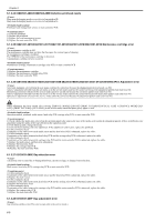
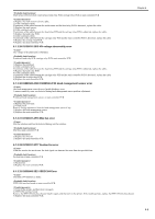
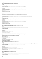
Chapter 6 6.1.3.24 03800501-280D/03800502-280E Defective printhead nozzle 0013-7178 Many non-discharging nozzles were detected on printhead R. Many non-discharging nozzles were detected on printhead L. Printhead, head management sensor, or main controller PCB 1) Clean the printhead. 2) Replace the printhead. 3) Replace the head management sensor. 4) Replace the main controller PCB. 6.1.3.25 03841201-2816/03841201-2817/03841101-2818/03841001-2819/03841001-281B Maintenance cartridge error 0013-7179 The maintenance cartridge is full. The maintenance cartridge does not have the free space for various types of cleaning. No maintenance cartridge is installed. The EEPROM of the maintenance cartridge is abnormal. A maintenance cartridge ID error occurred. Maintenance cartridge, maintenance cartridge relay PCB, or main controller PCB 1) Replace the maintenance cartridge. 2) Replace the maintenance cartridge relay PCB. 3) Replace the main controller PCB. 6.1.3.26 03010000-2820/03010000-2821/03010000-2822/03010000-2823/03130031-2F32/03010000-2F33/ Adjustment error 0013-7180 Auto head alignment selected from the user menu could not be carried out because the alignment pattern read result was NG. Auto LF adjustment selected from the user menu or in the service mode could not be carried out because the adjustment pattern read result was NG. Decentering correction selected in the service mode cannot be carried out because the correction pattern read result was NG. Auto LF adjustment selected from the user menu or in the service mode could not be carried out because the head check pattern read result was NG. Optical axis adjustment selected in the service mode cannot be carried out because the adjustment pattern read result was NG. When adjustment has been carried after selecting [SERVICE MODE]>[ADJUST]>[PRINT PATTERN]>[OPTICAL AXIS] or [SERVICE MODE]>[ADJUST]>[PRINT PATTERN]>[LF TUNING] in the service mode, check that photo glossy paper is used. Operation method, printhead, multi sensor, head relay PCB, carriage relay PCB, or main controller PCB 1) Check whether the media type selected on the operation panel is the same as the type of the media used to print the adjustment pattern. If they are different, retry adjustment using the media of the type selected on the operation panel. 2) If ink bleeds greatly, change the media. 3) Carry out head cleaning, and retry adjustment. If the adjustment result is poor, replace the printhead. 4) Cable continuity check If continuity of the cable between the multi sensor and the head relay PCB is abnormal, replace the cable. 5) Cable continuity check If continuity of the cable between the head relay PCB and the carriage relay PCB is abnormal, replace the cable. 6) Cable continuity check If continuity of the cable between the carriage relay PCB and the main controller PCB is abnormal, replace the cable. 7) Replace the multi sensor, and then retry adjustment. 8) Replace the head relay PCB. 9) Replace the carriage relay PCB. 10) Replace the main controller PCB. 6.1.3.27 03130031-260E Gap detection error 0013-7224 A detection error occurred due to damaged hardware, uncorrected gap, or damaged correction data. Multi sensor, head relay PCB, carriage relay PCB or main controller PCB 1) Cable continuity check If continuity of the cable between the multi sensor and the head relay PCB is abnormal, replace the cable. 2) Replace the multi sensor. 3) Cable continuity check If continuity of the cable between the head relay PCB and the carriage relay PCB is abnormal, replace the cable. 4) Replace the head relay PCB. 5) Cable continuity check If continuity of the cable between the carriage relay PCB and the main controller PCB is abnormal, replace the cable. 6) Replace the carriage relay PCB. 7) Replace the main controller PCB. 6.1.3.28 03130031-260F Gap adjustment error 0013-7228 Gap reference surface error (This error occurs only in the service mode.) 6-8
-
 1
1 -
2
-
3
-
4
-
5
-
6
-
7
-
8
-
9
-
10
-
11
-
12
-
13
-
14
-
15
-
16
-
17
-
18
-
19
-
20
-
21
-
22
-
23
-
24
-
25
-
26
-
27
-
28
-
29
-
30
-
31
-
32
-
33
-
34
-
35
-
36
-
37
-
38
-
39
-
40
-
41
-
42
-
43
-
44
-
45
-
46
-
47
-
48
-
49
-
50
-
51
-
52
-
53
-
54
-
55
-
56
-
57
-
58
-
59
-
60
-
61
-
62
-
63
-
64
-
65
-
66
-
67
-
68
-
69
-
70
-
71
-
72
-
73
-
74
-
75
-
76
-
77
-
78
-
79
-
80
-
81
-
82
-
83
-
84
-
85
-
86
-
87
-
88
-
89
-
90
-
91
-
92
-
93
-
94
-
95
-
96
-
97
-
98
-
99
-
100
-
101
-
102
-
103
-
104
-
105
-
106
-
107
-
108
-
109
-
110
-
111
-
112
-
113
-
114
-
115
-
116
-
117
-
118
-
119
-
120
-
121
-
122
-
123
-
124
-
125
-
126
-
127
-
128
-
129
-
130
-
131
-
132
-
133
-
134
-
135
-
136
-
 137
137 -
 138
138 -
 139
139 -
 140
140 -
 141
141 -
 142
142 -
 143
143 -
 144
144 -
 145
145 -
 146
146 -
 147
147 -
148
-
149
-
150
-
151
-
152
-
153
-
154
-
155
-
156
-
157
-
158
-
159
-
160
-
161
-
162
-
163
-
164
-
165
-
166
-
167
-
168
-
169
-
170
-
171
-
172
-
173
-
174
-
175
-
176
-
177
-
178
-
179
-
180
-
181
-
182
-
183
-
184
-
185
-
186
-
187
-
188
-
189
-
190
-
191
-
192
-
193
-
194
-
195
-
196
-
197
-
198
-
199
-
200
 |
 |
