Canon BU-47H instruction manual - Page 3
Installation Manualb-im-40113-5
 |
View all Canon BU-47H manuals
Add to My Manuals
Save this manual to your list of manuals |
Page 3 highlights
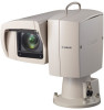
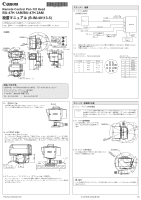
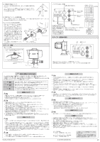
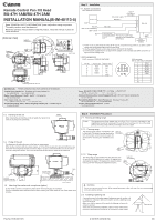
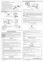
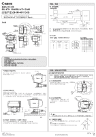
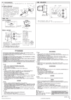
30° Receptacle 30˃ Remote Control Pan-Tilt Head BU-47H 1AM/BU-47H 2AM INSTALLATION MANUAL(B-IM-40113-5) Read "GENERAL SAFETY INFORMATION" (back side) before using the product. The safety cautions must be observed. Read this operation manual before using the product. Keep the manual in place for future reference. [External View] 170° Center of PAN rotation Center of TILT rotation sTwφILin4Tg30range φ620 PswANing range Optical axis 170° AUX CONT SD I V BS SYNC A-A section (Receptacle unit) 188 150 198 110 (Unit : mm) 34 80 92 50˃ 356 246 248 φ185 136 58 74.5 134.6 244 90 4xφ8.6 Mounting bolts M8×1.25 L=35 A A 164.5 Step1 Installation 1-1. System connections Short distance transmission Operation unit Cable *3 (Provided by the dealer) DC power supply *1 ● RS-422 *2 HD-SDI (MIC audio embedded) GEN LOCK Max.70m BU-47H SD Cable compensator (Commercially available) The maximum cable length depends on the compensation MIC performance. Washer (Commercially available) *1: Power of two or three times the rating 80 W may be consumed during power-on, so select a power supply with specifications that prevent a power failure. *2: Use the supplied RS-422 control cable connector (PRC05-P12F/TAJIMI). *3: Connect power supplied from a UL-approved AC adapter or the secondary side safety circuit of a UL- approved power supply circuit. 1-2.Pin assignment CONT. connector: PRC05-R12M/TAJIMI Pin No. A B D E J Input/output Input Output Input Output Signal name RX+ TX+ RX- TX- GND ̡̢ AUX connector: HR10A-10R-10S(71)/HIROSE 1 FPU 2 AUX1 3 AUX2 4 AUX3 5 AUX4 6 COM 7 8 9 10 Contact us. Please contact us if you have questions on the products. Canada: Canon Canada, Inc. Broadcast and Communications Div. Tel:+1(905)795-2012 Fax:+1(905)795-2087 Mexico: Canon Mexicana, S. de R.L. de C.V. Call Center Div. Tel:+52 55 5249 4905 USA : Canon U.S.A., Inc. ITCG METC Tel:+1(800) 423-5367 (Toll Free) Fax:+1(201) 807-3344 Asia and Hong Kong, S.A.R. : Canon Hongkong Company Ltd. ICP Marketing Div. Tel:+852-3191-2333 Korea 82)2-2191-8500 팩스 : (82)2-2191-8576 South and Southeast Asia : Canon Singapore Pte. Ltd. REG ICP Sales & Marketing Div. Tel:+65-6799-8888 Europe/Africa/Middle East : Canon Europe Ltd. Broadcast Products Div. Tel:+44(0)20-8588-8140 Fax:+44(0)20-8588-8929 Oceania: Canon Australia Pty. Ltd. CCI Div. Tel:+61(0)2-9805-2000 136 50 ° 1-3. Handling of the unit When carrying the unit, hold the unit by its handle. Be careful not to rotate the housing and head forcibly. Handle 1-4. Fixing of the unit The dimensions for drilling the holes in the floor are shown below. When the floor interferes with the cables, prepare φ 185 to 200 steel spacers to prevent interference. Use steel bolts with a length that enables a screw-in depth of 12 mm or more into the floor, and fix the unit securely to a strong floor surface. Use a level to check that the floor and the head unit are horizontal. Cable φ185 4 x φ8.6 mounting bolts M8 L=25+t2+12 or more 90 Spacer (steel) (if necessary) t1 = 12 mm or more φ185 ~ 200 25 t2 Floor surface 1-5. Attaching the washer and microphone (option) To also install a washer or microphone, please obtain the mounting jigs (not included). For more information about optional products, please contact your Canon dealer or your Canon sales representative. Step 2 Installation Precautions 2-1. Panning and tilting range ※ Note: The panning and tilting ranges may be off by 5% or so due to variations in the magnification caused by focusing and the pan-tilt head mounting error. Check the actual panning and tilting ranges before proceeding to set to the subject. 2-1-1. Panning range 170° The panning range extends 170 degrees to the Center of left and right. This yields a turning range with a PAN rotation 620 mm diameter which should be taken into account when selecting the installation loca- tion. φPs6Aw2Ni0ng range 170° 2-1-2. Tilting range The tilting range is approximately 430 mm when the pantilt head is inclined upward at an angle of 30 degrees and downward at an angle of 50 degrees: this should be taken into account when selecting the installation location. Center of TILT rotation swTiIφnLgT4r3a0nge WARNING Do not turn the lens toward the sun. When intense light enters at the TELE side, this can cause damage to the lens and the camera. 2-2. Installing a lightning rod If precautions need to be taken against lightning in case the system is to be installed on a hill-top or other such location, provide a lightning rod as shown in the figure. Make sure that the system will not touch the lightning rod when the camera is panned. In the case of a permanent installation, safety is further enhanced by providing a lightning-proof transformer for the system's power supply. 45° Lightning rod Pub No. B-IM-40113-5 © 2015.05 CANON INC. 3/6
-
 1
1 -
 2
2 -
 3
3 -
 4
4 -
 5
5 -
 6
6
 |
 |
