Canon PC400 Service Manual - Page 114
B. Power Supply PCB, C. Protection Mechanism for Power Supply Circuit
 |
View all Canon PC400 manuals
Add to My Manuals
Save this manual to your list of manuals |
Page 114 highlights
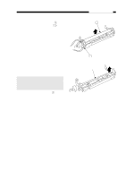
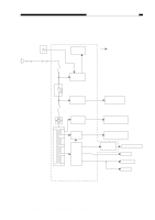
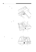
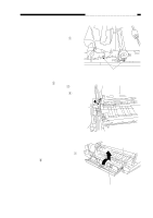
CHAPTER 7 EXTERNALS/AUXILIARY MECHANISMS B. Power Supply PCB The copier's power supply is a composite power supply in which one main transformer (T106) supplies DC power as well as power for high voltage and scanning lamp. AC power is supplied to the DC power supply when the power switch and door switch are turned ON. The DC power supply generates +24 V and +5 V. For auto power-off, the microprocessor causes the relay (RL101) to go OFF, thus cutting power supply. The copier is equipped with a sub power supply which provides the microprocessor with +5VDCL power for about 5 minutes after a condition associated 'E0' occurs; during this period, the copier is prevented from going ON to prevent damage by overheating the fixing heater. Note: The tolerances for the DC power supply are as follows: • +24VR ± 5% • +24 VU : +22 V to +46 V • +5 VL ± 2% • +5 V ± 10% C. Protection Mechanism for Power Supply Circuit The DC power supply circuit's AC power supply input is equipped with a fuse. The fuse blows if an overcurrent flows because of a short circuit in the 24V power, thus shutting out the output from the AC power supply circuit. If this happens, disconnect the copier's power cord, correct the cause of the problem, and replace the fuse. If the microprocessor detects an error on the AC or 24VDC line of the main transformer (T106), it causes the relay to go OFF, thus cutting the power output. If this happens, remove the cause and switch the copier ON to reset. 7-2 COPYRIGHT © 1998 CANON INC. CANON PC400/420/430,FC200/220 REV.0 JAN.1998 PRINTED IN JAPAN (IMPRIME AU JAPON)
-
 1
1 -
2
-
3
-
4
-
5
-
6
-
7
-
8
-
9
-
10
-
11
-
12
-
13
-
14
-
15
-
16
-
17
-
18
-
19
-
20
-
21
-
22
-
23
-
24
-
25
-
26
-
27
-
28
-
29
-
30
-
31
-
32
-
33
-
34
-
35
-
36
-
37
-
38
-
39
-
40
-
41
-
42
-
43
-
44
-
45
-
46
-
47
-
48
-
49
-
50
-
51
-
52
-
53
-
54
-
55
-
56
-
57
-
58
-
59
-
60
-
61
-
62
-
63
-
64
-
65
-
66
-
67
-
68
-
69
-
70
-
71
-
72
-
73
-
74
-
75
-
76
-
77
-
78
-
79
-
80
-
81
-
82
-
83
-
84
-
85
-
86
-
87
-
88
-
89
-
90
-
91
-
92
-
93
-
94
-
95
-
96
-
97
-
98
-
99
-
100
-
101
-
102
-
103
-
104
-
105
-
106
-
107
-
108
-
 109
109 -
 110
110 -
 111
111 -
 112
112 -
 113
113 -
 114
114 -
 115
115 -
 116
116 -
 117
117 -
 118
118 -
 119
119 -
120
-
121
-
122
-
123
-
124
-
125
-
126
-
127
-
128
-
129
-
130
-
131
-
132
-
133
-
134
-
135
-
136
-
137
-
138
-
139
-
140
-
141
-
142
-
143
-
144
-
145
-
146
-
147
-
148
-
149
-
150
-
151
-
152
-
153
-
154
-
155
-
156
-
157
-
158
-
159
-
160
-
161
-
162
-
163
-
164
-
165
-
166
-
167
-
168
-
169
-
170
-
171
-
172
-
173
-
174
-
175
-
176
-
177
-
178
-
179
-
180
-
181
-
182
-
183
-
184
-
185
-
186
-
187
-
188
-
189
-
190
-
191
-
192
-
193
-
194
-
195
-
196
-
197
 |
 |