Canon PC400 Service Manual - Page 123
C. DC Controller/DC Power, Supply PCB, Detaching the DC Controller/DC, Power Supply PCB, C
 |
View all Canon PC400 manuals
Add to My Manuals
Save this manual to your list of manuals |
Page 123 highlights
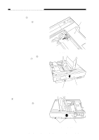
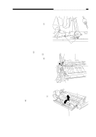
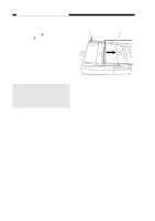
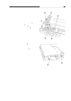
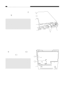
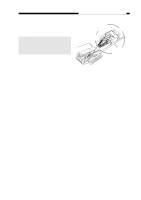
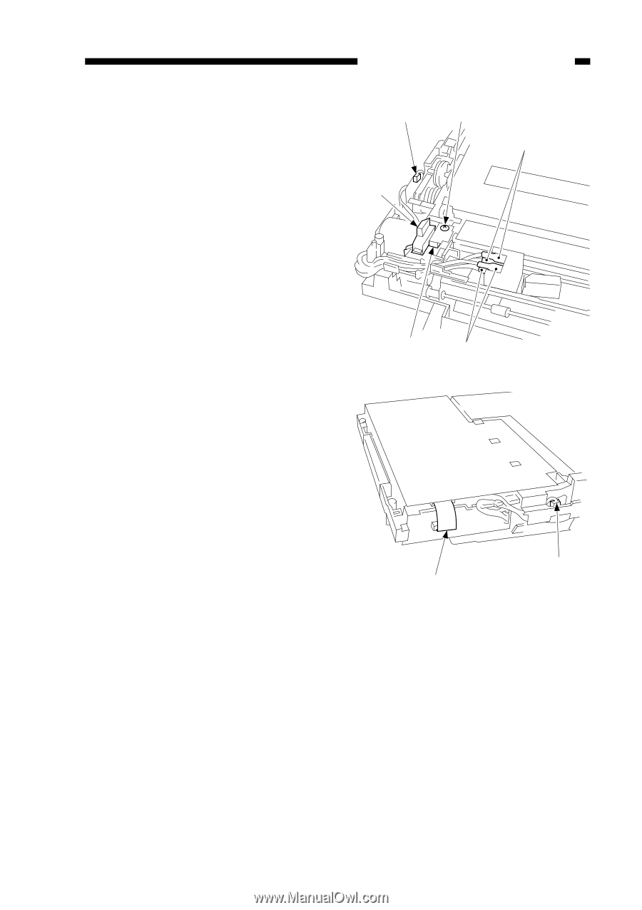
C. DC Controller/DC Power Supply PCB 1. Detaching the DC Controller/DC Power Supply PCB 1) Detach the body cover. 2) Remove the drive release arm q. 3) Remove the screw w, and discon- nect the two connectors e. 4) Disconnect the four fastons r. 5) Detach the bottom cover. CHAPTER 7 EXTERNALS/AUXILIARY MECHANISMS ÂÁ Ã À 6) Hold the flat cable t with both hands, and detach them from the connector by lifting them straight up. 7) Disconnect the connector y. ÂÃ Figure 7-201C Å Ä Figure 7-202C (front) COPYRIGHT © 1998 CANON INC. CANON PC400/420/430,FC200/220 REV.0 JAN.1998 PRINTED IN JAPAN (IMPRIME AU JAPON) 7-11
-
 1
1 -
2
-
3
-
4
-
5
-
6
-
7
-
8
-
9
-
10
-
11
-
12
-
13
-
14
-
15
-
16
-
17
-
18
-
19
-
20
-
21
-
22
-
23
-
24
-
25
-
26
-
27
-
28
-
29
-
30
-
31
-
32
-
33
-
34
-
35
-
36
-
37
-
38
-
39
-
40
-
41
-
42
-
43
-
44
-
45
-
46
-
47
-
48
-
49
-
50
-
51
-
52
-
53
-
54
-
55
-
56
-
57
-
58
-
59
-
60
-
61
-
62
-
63
-
64
-
65
-
66
-
67
-
68
-
69
-
70
-
71
-
72
-
73
-
74
-
75
-
76
-
77
-
78
-
79
-
80
-
81
-
82
-
83
-
84
-
85
-
86
-
87
-
88
-
89
-
90
-
91
-
92
-
93
-
94
-
95
-
96
-
97
-
98
-
99
-
100
-
101
-
102
-
103
-
104
-
105
-
106
-
107
-
108
-
109
-
110
-
111
-
112
-
113
-
114
-
115
-
116
-
117
-
 118
118 -
 119
119 -
 120
120 -
 121
121 -
 122
122 -
 123
123 -
 124
124 -
 125
125 -
 126
126 -
 127
127 -
 128
128 -
129
-
130
-
131
-
132
-
133
-
134
-
135
-
136
-
137
-
138
-
139
-
140
-
141
-
142
-
143
-
144
-
145
-
146
-
147
-
148
-
149
-
150
-
151
-
152
-
153
-
154
-
155
-
156
-
157
-
158
-
159
-
160
-
161
-
162
-
163
-
164
-
165
-
166
-
167
-
168
-
169
-
170
-
171
-
172
-
173
-
174
-
175
-
176
-
177
-
178
-
179
-
180
-
181
-
182
-
183
-
184
-
185
-
186
-
187
-
188
-
189
-
190
-
191
-
192
-
193
-
194
-
195
-
196
-
197
 |
 |
COPYRIGHT © 1998 CANON INC.
CANON PC400/420/430,FC200/220 REV.0 JAN.1998 PRINTED IN JAPAN (IMPRIME AU JAPON)
CHAPTER 7 EXTERNALS/AUXILIARY MECHANISMS
7-11
C. DC Controller/DC Power
Supply PCB
1.
Detaching the DC Controller/DC
Power Supply PCB
1)
Detach the body cover.
2)
Remove the drive release arm
q
.
3)
Remove the screw
w
, and discon-
nect the two connectors
e
.
4)
Disconnect the four fastons
r
.
5)
Detach the bottom cover.
Figure 7-201C
`
´
À
´
ˆ
ˆ
6)
Hold the flat cable
t
with both
hands, and detach them from the
connector by lifting them straight up.
7)
Disconnect the connector
y
.
Figure 7-202C (front)
˜
¯