Canon PC430 Service Manual - Page 47
Controlling the Copyboard Drive, B Front View
 |
UPC - 030275150322
View all Canon PC430 manuals
Add to My Manuals
Save this manual to your list of manuals |
Page 47 highlights
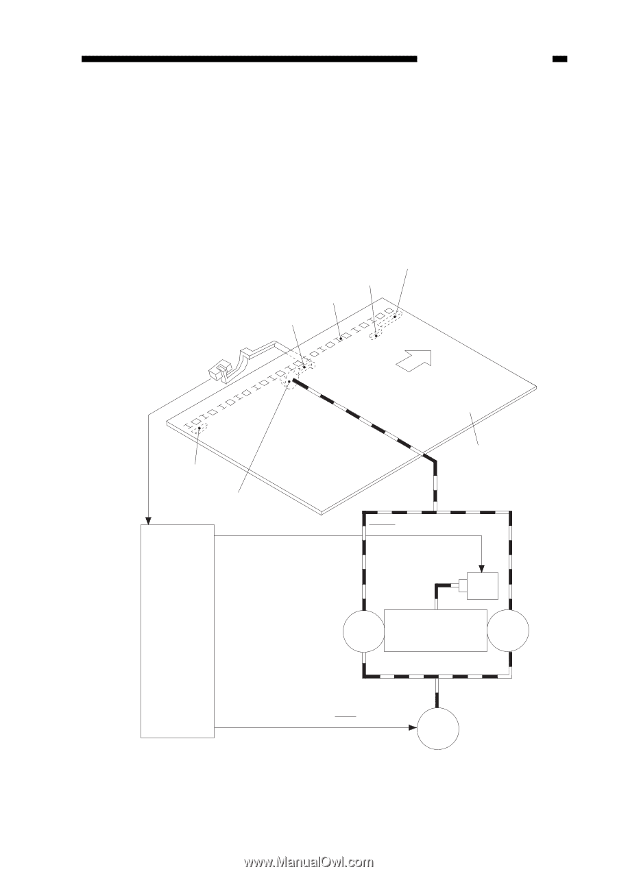
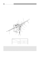
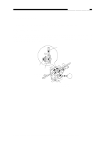
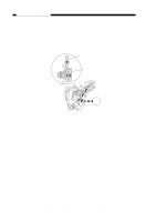
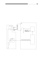
CHAPTER 3 EXPOSURE SYSTEM 2. Controlling the Copyboard Drive The copyboard is controlled for forward, reverse, and stop operations by the copyboard drive solenoid (SL2) and forward/ reverse switching mechanism. A photosensor (Q902) is provided on the copyboard drive assembly to monitor the position of the copyboard; as the copyboard moves, the cam found under the copyboard pushes the copyboard sensor lever to turn the photosensor ON or OFF. 'E2' is displayed if the copyboard fails to complete its movement within a specific period of time. In response to the signal from Q902, the DC controller controls the timing for paper transport and the movement (forward, reverse, stop) of the copyboard; see Table 3101B. Start position cam Registration cam Rack Copyboard position sensor lever Forward Copyboard position sensor Q902 Copyboard position sensor signal Reversal cam Copyboard glass J201 Copyboard drive gear -10 Copyboard drive solenoid drive command (CBSD) J201 -9 Copyboard drive solenoid SL2 DC controller/ DC power supply PCB Forward Forward/Reverse Reverse gear switching mechanism gear J201 -4 Main motor drive command (MMD) M1 Main motor Figure 3-102B Front View COPYRIGHT © 1998 CANON INC. CANON PC400/420/430,FC200/220 REV.0 JAN.1998 PRINTED IN JAPAN (IMPRIME AU JAPON) 3-3
-
 1
1 -
2
-
3
-
4
-
5
-
6
-
7
-
8
-
9
-
10
-
11
-
12
-
13
-
14
-
15
-
16
-
17
-
18
-
19
-
20
-
21
-
22
-
23
-
24
-
25
-
26
-
27
-
28
-
29
-
30
-
31
-
32
-
33
-
34
-
35
-
36
-
37
-
38
-
39
-
40
-
41
-
 42
42 -
 43
43 -
 44
44 -
 45
45 -
 46
46 -
 47
47 -
 48
48 -
 49
49 -
 50
50 -
 51
51 -
 52
52 -
53
-
54
-
55
-
56
-
57
-
58
-
59
-
60
-
61
-
62
-
63
-
64
-
65
-
66
-
67
-
68
-
69
-
70
-
71
-
72
-
73
-
74
-
75
-
76
-
77
-
78
-
79
-
80
-
81
-
82
-
83
-
84
-
85
-
86
-
87
-
88
-
89
-
90
-
91
-
92
-
93
-
94
-
95
-
96
-
97
-
98
-
99
-
100
-
101
-
102
-
103
-
104
-
105
-
106
-
107
-
108
-
109
-
110
-
111
-
112
-
113
-
114
-
115
-
116
-
117
-
118
-
119
-
120
-
121
-
122
-
123
-
124
-
125
-
126
-
127
-
128
-
129
-
130
-
131
-
132
-
133
-
134
-
135
-
136
-
137
-
138
-
139
-
140
-
141
-
142
-
143
-
144
-
145
-
146
-
147
-
148
-
149
-
150
-
151
-
152
-
153
-
154
-
155
-
156
-
157
-
158
-
159
-
160
-
161
-
162
-
163
-
164
-
165
-
166
-
167
-
168
-
169
-
170
-
171
-
172
-
173
-
174
-
175
-
176
-
177
-
178
-
179
-
180
-
181
-
182
-
183
-
184
-
185
-
186
-
187
-
188
-
189
-
190
-
191
-
192
-
193
-
194
-
195
-
196
-
197
 |
 |