Canon PC720 Service Manual - Page 72
measurements
 |
View all Canon PC720 manuals
Add to My Manuals
Save this manual to your list of manuals |
Page 72 highlights
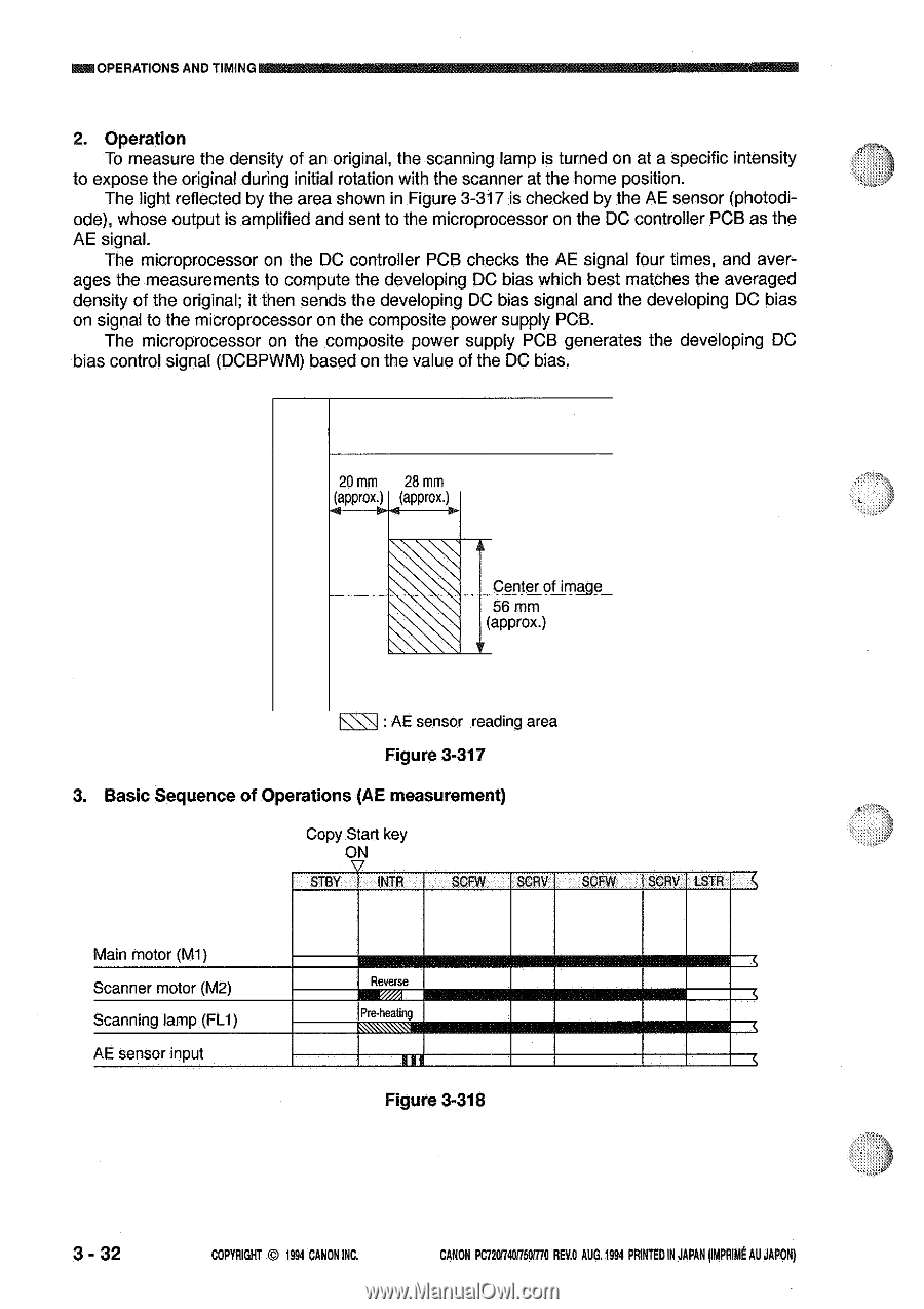
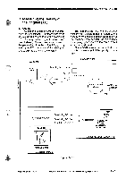
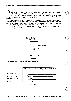
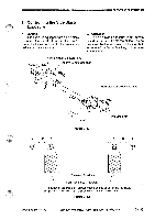
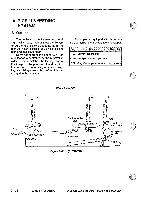
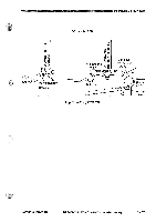
OPERATIONS AND TIMING 2. Operation To measure the density of an original, the scanning lamp is turned on at a specific intensity to expose the original during initial rotation with the scanner at the home position. The light reflected by the area shown in Figure 3-317 is checked by the AE sensor (photodi- ode), whose output is amplified and sent to the microprocessor on the DC controller PCB as the AE signal. The microprocessor on the DC controller PCB checks the AE signal four times, and averages the measurements to compute the developing DC bias which best matches the averaged density of the original; it then sends the developing DC bias signal and the developing DC bias on signal to the microprocessor on the composite power supply PCB. The microprocessor on the composite power supply PCB generates the developing DC bias control signal (DCBPWM) based on the value of the DC bias. 20 mm 28 mm (approx.) (approx.) Center of imAge 56 mm (approx.) : AE sensor reading area Figure 3-317 3. Basic Sequence of Operations (AE measurement) Copy Start key ON STBY INTR SCFW SCRV SCFW iSCRV LSTR Main motor (M-I) Scanner motor (M2) Scanning lamp (FU) AE sensor input "sRuevmerse Pre-heating 11 Figure 3-318 3 - 32 COPYRIGHT © 1994 CANON INC. CANON PC7201740501170 REV.O AUG.1994 PRINTED IN JAPAN (Ink AU JAPAN)
-
 1
1 -
2
-
3
-
4
-
5
-
6
-
7
-
8
-
9
-
10
-
11
-
12
-
13
-
14
-
15
-
16
-
17
-
18
-
19
-
20
-
21
-
22
-
23
-
24
-
25
-
26
-
27
-
28
-
29
-
30
-
31
-
32
-
33
-
34
-
35
-
36
-
37
-
38
-
39
-
40
-
41
-
42
-
43
-
44
-
45
-
46
-
47
-
48
-
49
-
50
-
51
-
52
-
53
-
54
-
55
-
56
-
57
-
58
-
59
-
60
-
61
-
62
-
63
-
64
-
65
-
66
-
 67
67 -
 68
68 -
 69
69 -
 70
70 -
 71
71 -
 72
72 -
 73
73 -
 74
74 -
 75
75 -
 76
76 -
 77
77 -
78
-
79
-
80
-
81
-
82
-
83
-
84
-
85
-
86
-
87
-
88
-
89
-
90
-
91
-
92
-
93
-
94
-
95
-
96
-
97
-
98
-
99
-
100
-
101
-
102
-
103
-
104
-
105
-
106
-
107
-
108
-
109
-
110
-
111
-
112
-
113
-
114
-
115
-
116
-
117
-
118
-
119
-
120
-
121
-
122
-
123
-
124
-
125
-
126
-
127
-
128
-
129
-
130
-
131
-
132
-
133
-
134
-
135
-
136
-
137
-
138
-
139
-
140
-
141
-
142
-
143
-
144
-
145
-
146
-
147
-
148
-
149
-
150
-
151
-
152
-
153
-
154
-
155
-
156
-
157
-
158
-
159
-
160
-
161
-
162
-
163
-
164
-
165
-
166
-
167
-
168
-
169
-
170
-
171
-
172
-
173
-
174
-
175
-
176
-
177
-
178
-
179
-
180
-
181
-
182
-
183
-
184
-
185
-
186
-
187
-
188
-
189
-
190
-
191
-
192
-
193
-
194
-
195
-
196
-
197
-
198
-
199
-
200
 |
 |