Cisco 5509 Installation Guide - Page 11
Installing the Chassis
 |
UPC - 746320139517
View all Cisco 5509 manuals
Add to My Manuals
Save this manual to your list of manuals |
Page 11 highlights
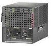
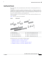
Unpacking and Installing the Controller Installing the Chassis The controller ships with rack mounting brackets and the desktop or shelf mounting rubber feet in a separate bag. An adjustable rack-mount kit is included for mounting the controller in a standard 19-inch (48.3 cm) equipment rack. A standard equipment rack has two unobstructed outer posts, a minimum depth between the front and rear mounting posts of 13 inches (33 cm), and a maximum depth of 32 inches (81.3 cm). You can also install the controller in a 2-post equipment rack. This kit is not suitable for racks with obstructions (such as a power strip) that could impair access to system components. Figure 3 shows the contents of the mounting kit. Figure 3 Mounting Kit 3 2 1 5 6 78 4 251199 1 Front brackets (2) 2 Rear bracket adapters (2) 3 Short slide-mount brackets (2) 4 Long slide-mount brackets (2) 5 12-24 x 0.75 in pan head screws (8) 6 10-32 x 0.75 in pan head screws (8) 7 M4x0.7 x 8mm flat head screws (6) 8 M3x0.5 x 6mm flat head screws (6) The following sections cover the different installation options: • Installing the Controller on a Desktop or Shelf, page 12 • Installing the Controller in a 4-Post Rack, page 12 • Installing the Controller in a 2-Post Rack-Flush Mount, page 16 • Installing the Controller in a 2-Post Rack-Mid-Mount, page 18 78-18998-01 Cisco 5500 Series Wireless Controller Installation Guide 11
-
 1
1 -
2
-
3
-
4
-
5
-
 6
6 -
 7
7 -
 8
8 -
 9
9 -
 10
10 -
 11
11 -
 12
12 -
 13
13 -
 14
14 -
 15
15 -
 16
16 -
17
-
18
-
19
-
20
-
21
-
22
-
23
-
24
-
25
-
26
-
27
-
28
-
29
-
30
-
31
-
32
-
33
-
34
 |
 |
