Cisco 5509 Installation Guide - Page 5
Checking the Controller LEDs - fan
 |
UPC - 746320139517
View all Cisco 5509 manuals
Add to My Manuals
Save this manual to your list of manuals |
Page 5 highlights
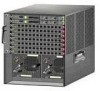
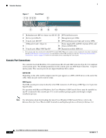
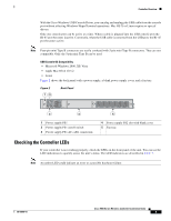
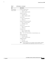
Controller Overview With the Cisco Windows USB Console Driver, you can plug and unplugg the USB cable from the console port without affecting Windows HyperTerminal operations. Mac OS X or Linux require no special drivers. Only one console port can be active at a time. When a cable is plugged into the USB console port the RJ-45 port becomes inactive. Conversely, when the USB cable is removed from the USB port, the RJ-45 port becomes active. Note Four-pin mini Type B connectors are easily confused with 5-pin mini Type B connectors. They are not compatible. Only the 5-pin mini Type B can be used. USB Console OS Compatibility • Microsoft Windows 2000, XP, Vista • Apple Mac OS X 10.5.2 • Linux Figure 2 shows the back panel with a power supply, a blank power supply cover, and a fan tray. Figure 2 12 Back Panel 251198 3 4 1 Power supply PS1 2 Power supply PS1 on/off switch 3 Power supply PS1 AC cable connection 5 4 Power supply PS2 slot with blank cover 5 Fan tray Checking the Controller LEDs If your controller is not working properly, check the LEDs on the front panel of the unit. You can use the LED indications to quickly assess the unit's status. The LED indicators are described in Table 1. Note An amber LED could indicate an error or a possible hardware failure. 78-18998-01 Cisco 5500 Series Wireless Controller Installation Guide 5
-
 1
1 -
 2
2 -
 3
3 -
 4
4 -
 5
5 -
 6
6 -
 7
7 -
 8
8 -
 9
9 -
 10
10 -
 11
11 -
12
-
13
-
14
-
15
-
16
-
17
-
18
-
19
-
20
-
21
-
22
-
23
-
24
-
25
-
26
-
27
-
28
-
29
-
30
-
31
-
32
-
33
-
34
 |
 |
