Cisco AIR-AP1020 Quick Start Guide - Page 23
Factory-Orderable Mounting Brackets
 |
UPC - 882658025952
View all Cisco AIR-AP1020 manuals
Add to My Manuals
Save this manual to your list of manuals |
Page 23 highlights
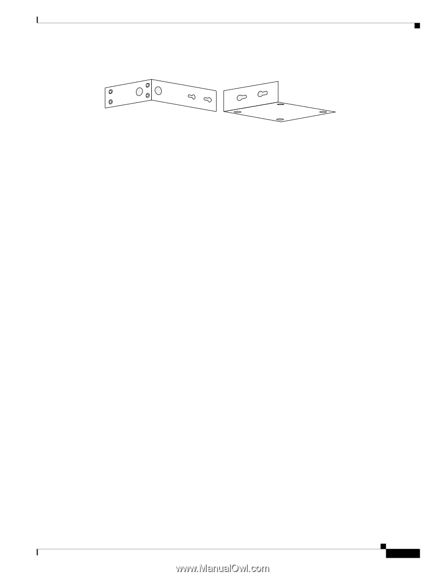
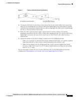
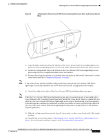
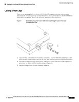
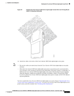
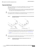
Installation and Configuration Figure 7 Factory-Orderable Mounting Brackets Preparing Mounting Locations 135661 A. Projection-mount bracket B. Flush-mount bracket 2. If necessary, drill holes for the various cables where they can be mostly hidden from casual view. When you are mounting the Cisco Aironet 1000 Series lightweight access point using an optional orderable projection-mount L-bracket (the one with two long legs), the cables can be routed through the 5/8-in. (15.9 mm) holes in the bracket. 3. Route the CAT-5, optional power supply, optional external antenna cable(s), and optional Kensington MicroSaver Security cables to where they can plug into the Cisco Aironet 1000 Series lightweight access point. Be sure to leave about 6 in. (15 cm) of slack in the cables for future modifications. 4. Attach the brackets to the wall or ceiling, or install screws for ceiling-mount base: - Where you are going to use the projection-mount or flush-mount bracket, use customer-supplied sheet metal, drywall, or other screws to attach the bracket to the ceiling or wall. - Where you are going to use the ceiling-mount base, install customer-supplied sheet metal, drywall, or other screws with 1/4 in. (6.35 mm) or smaller heads protruding from the ceiling about 0.1 in. (2.5 mm). You are now ready to install the Cisco Aironet 1000 Series 802.11a/b/g lightweight access points. Continue with "Mounting the Cisco Aironet 1000 Series Lightweight Access Points." AP1020/1030 Cisco Aironet 1000 Series IEEE 802.11a/b/g Lightweight Access Points with External Antennas - Quick Start Guide 78-17147-01 13
-
 1
1 -
2
-
3
-
4
-
5
-
6
-
7
-
8
-
9
-
10
-
11
-
12
-
13
-
14
-
15
-
16
-
17
-
 18
18 -
 19
19 -
 20
20 -
 21
21 -
 22
22 -
 23
23 -
 24
24 -
 25
25 -
 26
26 -
 27
27 -
 28
28 -
29
-
30
-
31
-
32
-
33
-
34
-
35
-
36
-
37
-
38
-
39
-
40
-
41
-
42
-
43
-
44
 |
 |