Cisco AIR-AP1131AG-E-K9 Hardware Installation Guide - Page 51
Removing the Back Cover
 |
View all Cisco AIR-AP1131AG-E-K9 manuals
Add to My Manuals
Save this manual to your list of manuals |
Page 51 highlights
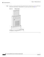
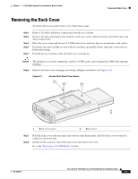
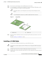
Chapter 4 2.4-GHz Radio Upgrade for Autonomous Access Points Removing the Back Cover Removing the Back Cover To remove the access point's back cover, follow these steps: Step 1 Step 2 Step 3 Step 4 Step 5 Remove all cables and power connections from the access point. Remove all static-generating items from the work area, such as plastic material, styrofoam cups, and other similar items. Place the access point and the new 2.4-GHz radio (in its antistatic bag) on an antistatic work surface. Discharge any static buildup on your body by touching a grounded surface (antistatic work surface) before proceeding. Position the access point so that the back cover is facing up. Caution The internal access point components and the 2.4-GHz radio can be damaged by ESD from improper handling. Step 6 Remove the back-cover retaining screw using a Philips screwdriver (see Figure 4-1). Figure 4-1 Access Point Back Cover Screw 1 2 95757 1 Back cover screw 2 Back cover Step 7 Step 8 Hold the front cover with one hand, and with the other hand gently slide the back cover towards the connector end of the unit. Gently lift the connector end of the back cover and remove the cover. Go to the "Removing a 2.4-GHz Radio" section. OL-4309-07 Cisco Aironet 1100 Series Access Point Hardware Installation Guide 4-3
-
 1
1 -
2
-
3
-
4
-
5
-
6
-
7
-
8
-
9
-
10
-
11
-
12
-
13
-
14
-
15
-
16
-
17
-
18
-
19
-
20
-
21
-
22
-
23
-
24
-
25
-
26
-
27
-
28
-
29
-
30
-
31
-
32
-
33
-
34
-
35
-
36
-
37
-
38
-
39
-
40
-
41
-
42
-
43
-
44
-
45
-
 46
46 -
 47
47 -
 48
48 -
 49
49 -
 50
50 -
 51
51 -
 52
52 -
 53
53 -
 54
54 -
 55
55 -
 56
56 -
57
-
58
-
59
-
60
-
61
-
62
-
63
-
64
-
65
-
66
-
67
-
68
-
69
-
70
-
71
-
72
-
73
-
74
-
75
-
76
-
77
-
78
-
79
-
80
-
81
-
82
-
83
-
84
-
85
-
86
-
87
-
88
-
89
-
90
-
91
-
92
-
93
-
94
-
95
-
96
-
97
-
98
-
99
-
100
-
101
-
102
-
103
-
104
-
105
-
106
-
107
-
108
-
109
-
110
-
111
-
112
-
113
-
114
-
115
-
116
 |
 |
