Cisco ASR1006-10G-HA/K9 Installation Guide - Page 18
Attaching the Cable-Management Brackets
 |
View all Cisco ASR1006-10G-HA/K9 manuals
Add to My Manuals
Save this manual to your list of manuals |
Page 18 highlights
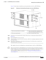
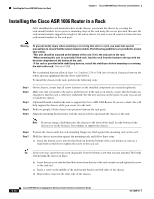
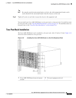
Attaching the Cable-Management Brackets Chapter 6 Cisco ASR 1006 Router Overview and Installation Step 2 Position the chassis until the rack-mounting flanges are flush against the mounting rails on the rack. Note Use the third hole up from the bottom of the rack-mount bracket and the third hole down from the top of the rack-mount bracket. See Figure 6-12 for position and location of the ear holes on the rack-mount bracket. Step 3 Step 4 Step 5 Step 6 Hold the chassis in position against the mounting rails while the second person finger-tightens a screw to the rack rails on each side of the chassis. Finger-tighten 4 more screws to the rack rails on each side of the chassis. Tighten all screws on each side to secure the chassis to the equipment rack. Use a level to verify that the tops of the two brackets are level, or use a measuring tape to verify that both brackets are the same distance from the top of the rack rails. This completes the procedure for installing the chassis in the rack. Proceed to the "Attaching the Cable-Management Brackets" section on page 6-18 to continue the installation. Attaching the Cable-Management Brackets The cable-management brackets are mounted on each rack-mount bracket on the chassis to provide cable management to both sides of the chassis (parallel with card orientation). These brackets are screw mounted to the rack-mount brackets to allow easy installation and removal of cables. The cable-management brackets for the Cisco ASR 1006 Router contain five independent cable-management "U" type features with four screws and provides cable dressing of each card module slots. For Cisco ASR 1000 SIPs, these brackets work in tandem with shared port adapter product feature cable-management device to allow installation and removal of adjacent cards without having to remove cables. Note Make certain that the cable-management bracket "U" type feature is facing upwards when you attach it to the chassis. Follow these steps to attach the cable-management brackets to both sides of the Cisco ASR 1006 Router in the rack: Step 1 Step 2 Align the cable-management bracket to the rack-mount bracket on one side of the Cisco ASR 1006 Router. The cable-management bracket aligns to the top hole of the chassis rack-mount bracket. Using a Phillips screwdriver, insert the screw through the cable-management bracket and into the rack-mount bracket and then tighten the screw. Note Use a screw from the package of four screws. Step 3 Using the bottom rack-mount ear hole, insert the screw through the cable-management bracket and into the rack-mount bracket. 6-18 Cisco ASR 1000 Series Aggregation Services Routers Hardware Installation Guide OL-13208-09
-
 1
1 -
2
-
3
-
4
-
5
-
6
-
7
-
8
-
9
-
10
-
11
-
12
-
 13
13 -
 14
14 -
 15
15 -
 16
16 -
 17
17 -
 18
18 -
 19
19 -
 20
20 -
 21
21 -
 22
22 -
 23
23 -
24
-
25
-
26
-
27
-
28
-
29
-
30
-
31
-
32
-
33
-
34
-
35
-
36
 |
 |
