Cisco ASR1006-10G-HA/K9 Installation Guide - Page 6
Installation Methods, General Rack Installation Guidelines
 |
View all Cisco ASR1006-10G-HA/K9 manuals
Add to My Manuals
Save this manual to your list of manuals |
Page 6 highlights
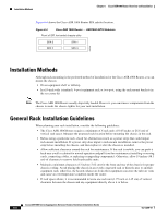
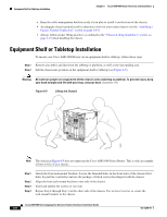
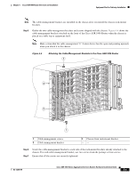
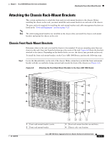
Installation Methods Chapter 6 Cisco ASR 1006 Router Overview and Installation Figure 6-4 shows the Cisco ASR 1006 Router SPA subslot location. Figure 6-4 Cisco ASR 1006 Router - ASR1000-SIP10 Subslots Front of SIP, horizontal chassis slots SPA 0 SPA 2 SPA 1 SPA 3 231508 Installation Methods Although rack-mounting is the preferred method of installation for the Cisco ASR 1006 Router, you can mount the chassis: • On an equipment shelf or tabletop • In a19-inch wide (standard), 4-post equipment rack or two-post, using the rack-mount brackets in the accessory kit Note The Cisco ASR 1006 Router usually ships fully loaded. However, you can remove components from the chassis to make the chassis lighter for your rack installation. General Rack Installation Guidelines When planning your rack installation, consider the following guidelines: • The Cisco ASR 1006 Router requires a minimum of 6 rack units (10.45 inches or 26.6 cm) of vertical rack space. Measure the proposed rack location before mounting the chassis in the rack. • Before using a particular rack, check for obstructions (such as a power strip) that could impair rack-mount installation. If a power strip does impair a rack-mount installation, remove the power strip before installing the chassis, and then replace it after the chassis is installed. • Allow sufficient clearance around the rack for maintenance. If the rack is mobile, you can push it back near a wall or cabinet for normal operation and pull it out for maintenance (installing or moving cards, connecting cables, or replacing or upgrading components). Otherwise, allow 19 inches (48.3 cm) of clearance to remove field-replaceable units. • Maintain a minimum clearance of 3 inches (7.62 cm) for the front and rear of the chassis for proper chassis cooling. Avoid placing the chassis in an overly congested rack or directly next to another equipment rack; otherwise, the heated exhaust air from other equipment can enter the inlet air vents and cause an overtemperature condition inside the router. • If rack space allows, it is recommended to leave one rack unit (1.75 inch or 4.45 cm) of vertical clearance between the chassis and any equipment directly above it or below. Cisco ASR 1000 Series Aggregation Services Routers Hardware Installation Guide 6-6 OL-13208-09
-
 1
1 -
 2
2 -
 3
3 -
 4
4 -
 5
5 -
 6
6 -
 7
7 -
 8
8 -
 9
9 -
 10
10 -
 11
11 -
 12
12 -
13
-
14
-
15
-
16
-
17
-
18
-
19
-
20
-
21
-
22
-
23
-
24
-
25
-
26
-
27
-
28
-
29
-
30
-
31
-
32
-
33
-
34
-
35
-
36
 |
 |
