Cisco PIX 506E Quick Start Guide - Page 5
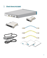
Step 1, Follow these steps to power on the PIX Firewall
 |
UPC - 746320661315
View all Cisco PIX 506E manuals
Add to My Manuals
Save this manual to your list of manuals |
Page 5 highlights
67932 ACT LINK ETHERNET 1 ACT LINK ETHERNET 0 DC POWER USB CONSOLE INPUT DC POWER INPUT Cisco PIX 506E Follow these steps to power on the PIX Firewall: Power supply Step 1 Step 2 Step 3 Step 4 Connect the small, square connector of the power supply cable to the power connector on the rear panel. Check the power LED, if it is green, then the device is powered on. For more information, refer to the "Check the LEDs" section on page 11. Connect the AC power connector of the power supply input cable to an electrical outlet. Set the power switch to the on (|) position. 5
-
 1
1 -
 2
2 -
 3
3 -
 4
4 -
 5
5 -
 6
6 -
 7
7 -
 8
8 -
 9
9 -
 10
10 -
 11
11 -
12
-
13
-
14
-
15
-
16
 |
 |

5
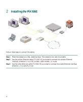
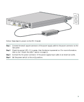
Follow these steps to power on the PIX Firewall:
Step 1
Connect the small, square connector of the power supply cable to the power connector on the
rear panel.
Step 2
Check the power LED, if it is green, then the device is powered on. For more information,
refer to the “Check the LEDs” section on page 11.
Step 3
Connect the AC power connector of the power supply input cable to an electrical outlet.
Step 4
Set the power switch to the on (|) position.
ETHERNET 0
ETHERNET 1
CONSOLE
LINK
DC
POWER
INPUT
USB
ACT
LINK
ACT
Cisco PIX 506E
DC
POWER
INPUT
67932
Power supply