Cisco SFS-7012 User Guide - Page 44
Removing a Module or Blank, Installing the Spine and Leaf Modules
 |
View all Cisco SFS-7012 manuals
Add to My Manuals
Save this manual to your list of manuals |
Page 44 highlights
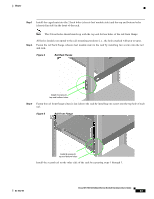
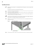
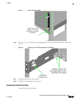
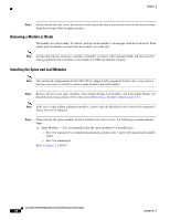
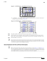
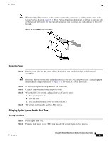
Chapter Step 1 On the switch fan side, insert the notches on the top of the fascia into the two slots on the chassis frame. Snap the bottom of the faceplate in place. Removing a Module or Blank The handles are self-locking. To unlock, push up on the handles to disengage from the lock notch. Then gently pull the handles out and slide the module out of the slot. Note If removing, but not replacing a module, remember to replace with a module blank. All slots must be either populated with a module or have blanks for EMI and thermal integrity. Installing the Spine and Leaf Modules Note The purchased configuration for the SFS 7012 is shipped fully populated. Follow these steps when it becomes necessary to install or replace spine modules and leaf modules. Step 1 Remove the necessary spine modules, spine module blanks, leaf modules, and leaf module blanks. For detailed instructions, please refer to the section Removing a Module or Blank, page 2-26. Note If the user is only adding additional modules, remove only the blank(s) for the slot(s) to be populated. These will not be replaced. Step 1 When placing the spine modules and leaf modules into chassis slots, the following recommendations apply: a. Spine Modules - It is recommended that the spine module(s) be installed into: - Slot 1 for managed. For redundant management, populate slots 1 and 2 with management-capable spines. - Slot 3 for unmanaged. Refer to Figure 2-9 below: Cisco SFS 7012 InfiniBand Server Switch Hardware Users Guide 26 OL-8787-04
-
 1
1 -
2
-
3
-
4
-
5
-
6
-
7
-
8
-
9
-
10
-
11
-
12
-
13
-
14
-
15
-
16
-
17
-
18
-
19
-
20
-
21
-
22
-
23
-
24
-
25
-
26
-
27
-
28
-
29
-
30
-
31
-
32
-
33
-
34
-
35
-
36
-
37
-
38
-
 39
39 -
 40
40 -
 41
41 -
 42
42 -
 43
43 -
 44
44 -
 45
45 -
 46
46 -
 47
47 -
 48
48 -
 49
49 -
50
-
51
-
52
-
53
-
54
-
55
-
56
-
57
-
58
-
59
-
60
-
61
-
62
-
63
-
64
-
65
-
66
-
67
-
68
-
69
-
70
-
71
-
72
-
73
-
74
-
75
-
76
-
77
-
78
-
79
-
80
-
81
-
82
-
83
-
84
-
85
-
86
-
87
-
88
-
89
-
90
-
91
-
92
-
93
-
94
-
95
-
96
-
97
-
98
-
99
-
100
-
101
-
102
-
103
-
104
-
105
-
106
-
107
-
108
-
109
-
110
-
111
-
112
-
113
-
114
-
115
-
116
 |
 |