Cisco WS-C5500-S3-E3A-RF Installation Guide - Page 21
Preventing ESD Damage, Step 1, Caution
 |
View all Cisco WS-C5500-S3-E3A-RF manuals
Add to My Manuals
Save this manual to your list of manuals |
Page 21 highlights
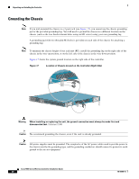
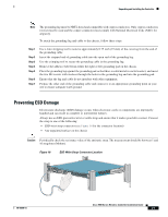
Unpacking and Installing the Controller Note The grounding lug must be NRTL listed and compatible with copper conductors. Only copper conductors (wires) must be used and the copper conductor must comply with National Electrical Code (NEC) for ampacity. To attach the grounding lug and cable to the chassis, follow these steps: Step 1 Step 2 Step 3 Step 4 Step 5 Step 6 Step 7 Use a wire-stripping tool to remove approximately 0.75 inch (19 mm) of the covering from the end of the grounding cable. Insert the stripped end of grounding cable into the open end of the grounding lug. Use the crimping tool to secure the grounding cable in the grounding lug. Remove the adhesive label from either the right or left grounding pad on the chassis. Place the grounding lug against the grounding pad so that there is solid metal-to-metal contact, and insert the two M4 screws with washers through the holes in the grounding lug and into the grounding pad. Ensure that the lug and cable do not interfere with other equipment. Prepare the other end of the grounding cable and connect it to an appropriate grounding point in your site to ensure adequate earth ground. Preventing ESD Damage Electrostatic discharge (ESD) damage occurs when electronic cards or components are improperly handled and can result in complete or intermittent failures. Always use an ESD-preventive wrist or ankle strap and ensure that it makes good skin contact. Connect the strap to one of the following: • ESD wrist strap connector (see Figure 18 for the connector location) • Any unpainted surface on the chassis Caution Periodically check the resistance value of the antistatic strap. The measurement should be between 1 and 10 megohms (Mohms). Figure 18 ESD Wrist Strap Connector Location RP SP USB0 USB1 CONSOLE EN EN Cisco 5500 Series Wireless Controller 12 34 56 78 Model 5508 PS1 PS2 SYS ACT 251239 78-18998-01 Cisco 5500 Series Wireless Controller Installation Guide 21
-
 1
1 -
2
-
3
-
4
-
5
-
6
-
7
-
8
-
9
-
10
-
11
-
12
-
13
-
14
-
15
-
 16
16 -
 17
17 -
 18
18 -
 19
19 -
 20
20 -
 21
21 -
 22
22 -
 23
23 -
 24
24 -
 25
25 -
 26
26 -
27
-
28
-
29
-
30
-
31
-
32
-
33
-
34
 |
 |
