Cisco WS-C5500-S3-E3A-RF Installation Guide - Page 29
Tools and Equipment Required, Step 1
 |
View all Cisco WS-C5500-S3-E3A-RF manuals
Add to My Manuals
Save this manual to your list of manuals |
Page 29 highlights
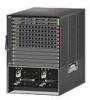
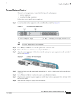
Using the Startup Wizard Tools and Equipment Required To install a power supply unit, you need the following tools and equipment: • A power supply unit • A number 1 Phillips screwdriver Follow these steps to install a power supply unit. Step 1 Locate the empty power supply slot on the controller's back panel. See Figure 19. Figure 19 Controller Power Supply Slots 1 2 251205 1 Slot 1 with power supply 2 Slot 2 with empty power supply slot with cover Note The power supply units are hot swappable. Step 2 Step 3 Step 4 Use a Phillips screwdriver to loosen the captive screw on the slot cover. Remove the slot cover and store it in a safe place for future use. Align the power supply unit with the slot so that the unit's power input receptacle is on the left side of the slot. See Figure 20. Figure 20 Inserting the Power Supply 251206 Step 5 Step 6 Step 7 Step 8 Gently but firmly push the power supply unit into the slot until it is firmly seated in the card electrical connector. Use a Phillips screwdriver to tighten the captive screw. Do not overtighten. Plug the power cord into the power supply unit and the other end into a grounded 100 to 240 VAC 50/60 Hz electrical outlet. Make sure that both power supply units are turned on. 78-18998-01 Cisco 5500 Series Wireless Controller Installation Guide 29
-
 1
1 -
2
-
3
-
4
-
5
-
6
-
7
-
8
-
9
-
10
-
11
-
12
-
13
-
14
-
15
-
16
-
17
-
18
-
19
-
20
-
21
-
22
-
23
-
 24
24 -
 25
25 -
 26
26 -
 27
27 -
 28
28 -
 29
29 -
 30
30 -
 31
31 -
 32
32 -
 33
33 -
 34
34
 |
 |
