Compaq Evo n1020v Maintenance and Service Guide - Page 123
Removing a Mini PCI Communications Board
 |
View all Compaq Evo n1020v manuals
Add to My Manuals
Save this manual to your list of manuals |
Page 123 highlights
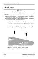
Removal and Replacement Procedures 7. Disconnect the modem cable from the mini PCI communications board 1 (Figure 5-13). 8. Spread the retaining tabs 2 on each side of the mini PCI communications board. The board releases and rests at an angle. 9. Remove the board by pulling it away from the socket at an angle 3. Figure 5-13. Removing a Mini PCI Communications Board Reverse the preceding procedures to install a mini PCI communications board. Maintenance and Service Guide 5-17
-
 1
1 -
2
-
3
-
4
-
5
-
6
-
7
-
8
-
9
-
10
-
11
-
12
-
13
-
14
-
15
-
16
-
17
-
18
-
19
-
20
-
21
-
22
-
23
-
24
-
25
-
26
-
27
-
28
-
29
-
30
-
31
-
32
-
33
-
34
-
35
-
36
-
37
-
38
-
39
-
40
-
41
-
42
-
43
-
44
-
45
-
46
-
47
-
48
-
49
-
50
-
51
-
52
-
53
-
54
-
55
-
56
-
57
-
58
-
59
-
60
-
61
-
62
-
63
-
64
-
65
-
66
-
67
-
68
-
69
-
70
-
71
-
72
-
73
-
74
-
75
-
76
-
77
-
78
-
79
-
80
-
81
-
82
-
83
-
84
-
85
-
86
-
87
-
88
-
89
-
90
-
91
-
92
-
93
-
94
-
95
-
96
-
97
-
98
-
99
-
100
-
101
-
102
-
103
-
104
-
105
-
106
-
107
-
108
-
109
-
110
-
111
-
112
-
113
-
114
-
115
-
116
-
117
-
 118
118 -
 119
119 -
 120
120 -
 121
121 -
 122
122 -
 123
123 -
 124
124 -
 125
125 -
 126
126 -
 127
127 -
 128
128 -
129
-
130
-
131
-
132
-
133
-
134
-
135
-
136
-
137
-
138
-
139
-
140
-
141
-
142
-
143
-
144
-
145
-
146
-
147
-
148
-
149
-
150
-
151
-
152
-
153
-
154
-
155
-
156
-
157
-
158
-
159
-
160
-
161
-
162
-
163
-
164
-
165
-
166
-
167
-
168
-
169
-
170
-
171
-
172
-
173
-
174
-
175
-
176
-
177
-
178
-
179
-
180
-
181
-
182
-
183
-
184
-
185
-
186
-
187
-
188
-
189
-
190
-
191
-
192
-
193
-
194
-
195
-
196
-
197
-
198
-
199
-
200
-
201
-
202
-
203
-
204
-
205
-
206
-
207
-
208
-
209
-
210
-
211
-
212
-
213
-
214
-
215
-
216
-
217
-
218
-
219
 |
 |

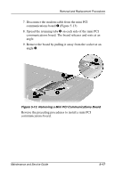
Removal and Replacement Procedures
Maintenance and Service Guide
5–17
7. Disconnect the modem cable from the mini PCI
communications board
1
(Figure 5-13).
8. Spread the retaining tabs
2
on each side of the mini PCI
communications board. The board releases and rests at an
angle.
9. Remove the board by pulling it away from the socket at an
angle
3
.
Figure 5-13. Removing a Mini PCI Communications Board
Reverse the preceding procedures to install a mini PCI
communications board.