Compaq Mini 311c-1100 HP Pavilion dm1 HP Mini 311 Compaq Mini 311 - Maintenanc - Page 52
Remove the Phillips PM2.0×4.0 screw, WLAN modules are designed with a notch
 |
View all Compaq Mini 311c-1100 manuals
Add to My Manuals
Save this manual to your list of manuals |
Page 52 highlights
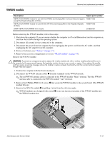
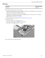
Removal and replacement procedures 4. Disconnect the WLAN antenna cables 1 from the terminals on the WLAN module. ✎ The black WLAN antenna cable is connected to the WLAN module "Main" terminal. The white WLAN antenna cable is connected to the WLAN module "Aux" terminal. 5. Remove the Phillips PM2.0×4.0 screw 2 that secures the WLAN module to the system board. (The WLAN module tilts up.) 6. Remove the WLAN module 3 by pulling it away from the slot at an angle. ✎ WLAN modules are designed with a notch 4 to prevent incorrect insertion of the WLAN module into the WLAN module slot. Reverse this procedure to install the WLAN module. 4-12 Maintenance and Service Guide
-
 1
1 -
2
-
3
-
4
-
5
-
6
-
7
-
8
-
9
-
10
-
11
-
12
-
13
-
14
-
15
-
16
-
17
-
18
-
19
-
20
-
21
-
22
-
23
-
24
-
25
-
26
-
27
-
28
-
29
-
30
-
31
-
32
-
33
-
34
-
35
-
36
-
37
-
38
-
39
-
40
-
41
-
42
-
43
-
44
-
45
-
46
-
 47
47 -
 48
48 -
 49
49 -
 50
50 -
 51
51 -
 52
52 -
 53
53 -
 54
54 -
 55
55 -
 56
56 -
 57
57 -
58
-
59
-
60
-
61
-
62
-
63
-
64
-
65
-
66
-
67
-
68
-
69
-
70
-
71
-
72
-
73
-
74
-
75
-
76
-
77
-
78
-
79
-
80
-
81
-
82
-
83
-
84
-
85
-
86
-
87
-
88
-
89
-
90
-
91
-
92
-
93
-
94
-
95
-
96
-
97
-
98
-
99
-
100
-
101
-
102
-
103
-
104
-
105
-
106
-
107
-
108
-
109
-
110
-
111
-
112
-
113
-
114
-
115
-
116
-
117
-
118
-
119
-
120
-
121
-
122
-
123
-
124
-
125
-
126
-
127
-
128
-
129
-
130
-
131
-
132
-
133
-
134
-
135
-
136
-
137
-
138
 |
 |
4–12
Maintenance and Service Guide
Removal and replacement procedures
4. Disconnect the WLAN antenna cables
1
from the terminals on the WLAN module.
✎
The black WLAN antenna cable is connected to the WLAN module “Main” terminal. The white WLAN
antenna cable is connected to the WLAN module “Aux” terminal.
5. Remove the Phillips PM2.0×4.0 screw
2
that secures the WLAN module to the system board. (The WLAN
module tilts up.)
6. Remove the WLAN module
3
by pulling it away from the slot at an angle.
✎
WLAN modules are designed with a notch
4
to prevent incorrect insertion of the WLAN module into
the WLAN module slot.
Reverse this procedure to install the WLAN module.