Craftsman 88835 Operation Manual - Page 21
Shave Plate And Skid Shoes
 |
View all Craftsman 88835 manuals
Add to My Manuals
Save this manual to your list of manuals |
Page 21 highlights
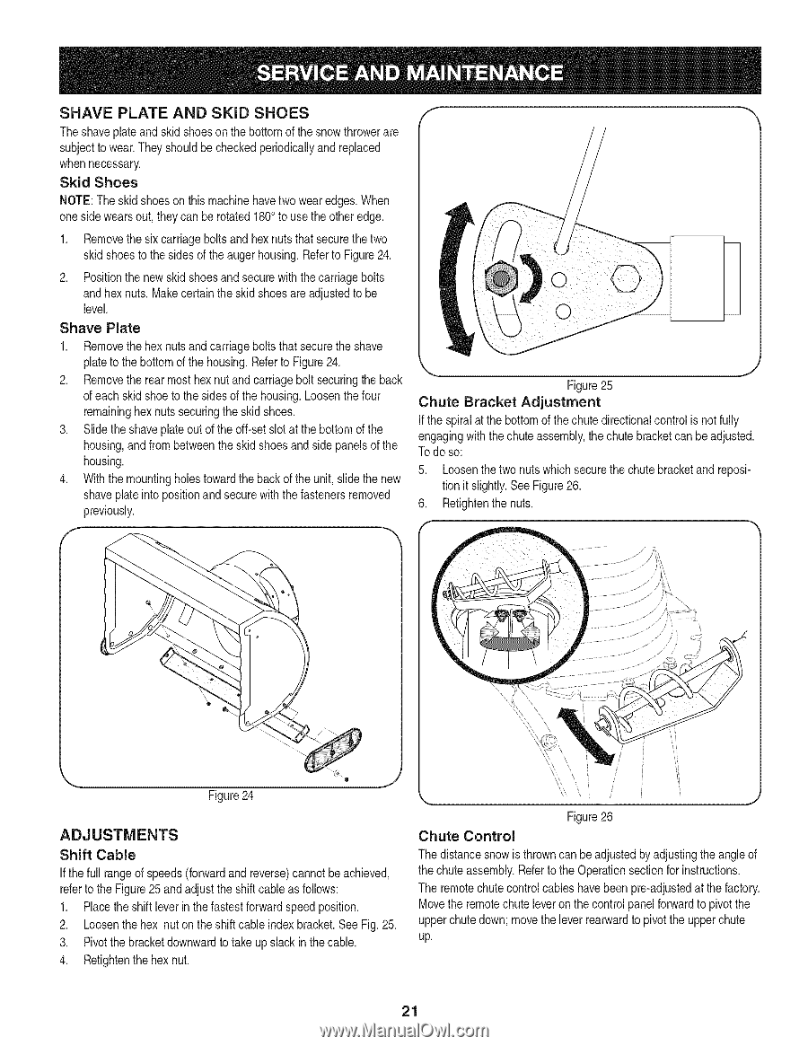
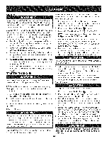
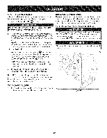
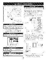
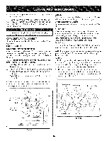
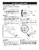
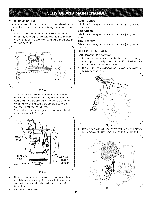
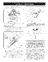
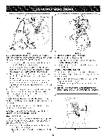
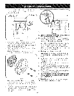
SHAVE PLATE AND SKiD SHOES Theshaveplateand skid shoeson the bottomof the snowthrowerare subjectto wear.They shouldbe checkedperiodicallyand replaced whennecessary. Skid Shoes NOTE:Theskid shoes on this machinehavetwo wearedges.When one sidewearsout, theycan be rotated1800to usethe otheredge. 1. Removethesix carriagebolts and hexnuts that securethe two skid shoesto the sides of the augerhousing.Referto Figure24. 2. Positionthe new skid shoesand securewith the carriagebolts and hex nuts.Makecertainthe skid shoesare adjustedto be level. k Shave Plate 1. Removethehex nuts and carriagebolts that securethe shave plateto the bottomof the housing.Referto Figure24. J 2. Removethe rearmost hexnutand carriagebolt securingthe back Figure25 of eachskid shoeto the sides of the housing.Loosenthefour Chute Bracket Adjustment remaininghexnuts securingthe skid shoes. If the spiralat the bottomof thechute directionalcontrolis notfully 3. Slide theshaveplateout of the off-set slotat thebottomof the engagingwith thechute assembly,the chutebracketcan be adjusted. housing,and from betweenthe skid shoesand side panelsof the Todo so: housing. 4. With the mountingholestowardthe back of the unit, slidethe new 5. Loosenthetwo nutswhich securethe chute bracketand reposi- shaveplateinto positionand securewith the fastenersremoved tion it slightly.See Figure26. previously. 6. Retightenthenuts. f Figure24 ADJUSTMENTS Shift Cable If thefull rangeof speeds(forwardand reverse)cannotbe achieved, referto the Figure25 and adjustthe shiftcable as follows: 1. Placethe shiftleverin thefastestforwardspeedposition. 2. Loosenthe hex nuton the shiftcable indexbracket.See Fig. 25. 3. Pivotthe bracketdownwardto take up slack in the cable. 4. Retightenthehex nut. Figure26 Chute Control The distancesnow is throwncanbe adjustedbyadjustingthe angle of the chute assembly.Referto the Operationsectionfor instructions. The remotechutecontrolcables havebeen pre-adjustedat the factory. Movethe remotechute leveron the controlpanelforwardto pivot the upperchutedown; movethe leverrearwardto pivotthe upperchute up. 21
-
 1
1 -
2
-
3
-
4
-
5
-
6
-
7
-
8
-
9
-
10
-
11
-
12
-
13
-
14
-
15
-
 16
16 -
 17
17 -
 18
18 -
 19
19 -
 20
20 -
 21
21 -
 22
22 -
 23
23 -
 24
24 -
 25
25 -
 26
26 -
27
-
28
-
29
-
30
-
31
-
32
-
33
-
34
-
35
-
36
-
37
-
38
-
39
-
40
-
41
-
42
-
43
-
44
-
45
-
46
-
47
-
48
-
49
-
50
-
51
-
52
-
53
-
54
-
55
-
56
-
57
-
58
-
59
-
60
-
61
-
62
-
63
-
64
-
65
-
66
-
67
-
68
-
69
-
70
-
71
-
72
-
73
-
74
-
75
-
76
 |
 |