Craftsman 88957 Operation Manual - Page 23
NOTE: Whenreassembling
 |
View all Craftsman 88957 manuals
Add to My Manuals
Save this manual to your list of manuals |
Page 23 highlights
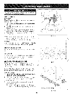
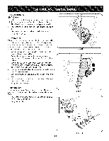
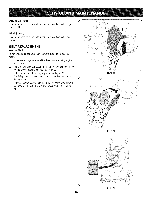
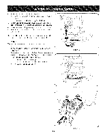
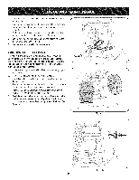
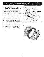
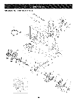
NOTE:Be carefulnot to damagethe threadson the shaft, 7. Carefullypositionthe hexshaftdownwardand to the left before carefullyslidingthe frictionwheelassemblyoff the shaft. See Figure31. NOTE: If you'rereplacingthe frictionwheelassemblyas a whole, discardthe wornpartand slidethe newpart ontothe hexshaft. Followthe stepsabovein reverseorder to reassemblecomponents.If you'redisassemblingthe frictionwheeland replacingonly the rubber ring,proceedas follows: 1. Removethefour screwswhich securethe frictionwheel'sside platestogether. See Figure32. 2. Removethe rubberring from betweenthe plates. 3. Reassemblethe side plateswith a newrubberring. NOTE: Whenreassemblingthe frictionwheelassembly,makesure that the rubberring is centeredand seatedproperlybetweenthe side plates.Tighteneachscrewonlyone rotationbeforeturningthe wheel clockwiseand proceedingwith the next screw.Repeatthis process severaltimes toensurethe platesare securedwith equalforce (between6 ft-lbsand 9 ft-lbs). 4. Slide the frictionwheelassemblybackonto the hexshaftand follow thestepsabovein reverseorder to reassemble components. 5. Performthe testpreviouslydescribedin the DriveControl section. Figure31 ... j Figure32 23
-
 1
1 -
2
-
3
-
4
-
5
-
6
-
7
-
8
-
9
-
10
-
11
-
12
-
13
-
14
-
15
-
16
-
17
-
 18
18 -
 19
19 -
 20
20 -
 21
21 -
 22
22 -
 23
23 -
 24
24 -
 25
25 -
 26
26 -
 27
27 -
 28
28 -
29
-
30
-
31
-
32
-
33
-
34
-
35
-
36
-
37
-
38
-
39
-
40
-
41
-
42
-
43
-
44
-
45
-
46
-
47
-
48
-
49
-
50
-
51
-
52
-
53
-
54
-
55
-
56
-
57
-
58
-
59
-
60
-
61
-
62
-
63
-
64
-
65
-
66
-
67
-
68
-
69
-
70
-
71
-
72
 |
 |
