Craftsman M2500R4 Operation Manual - Page 12
Assembly And Adjustments
 |
View all Craftsman M2500R4 manuals
Add to My Manuals
Save this manual to your list of manuals |
Page 12 highlights
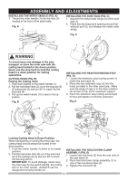
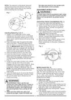
ASSEMBLY AND ADJUSTMENTS INSTALLING THE MITER HANDLE (FIG. A) 1. Thread the miter handle (1) into the hole (2) located at the front of the miter table. Fig. A INSTALLING THE DUST BAG (FIG. C) 1. Squeeze the metal collar wings (2) of the dust bag (1). 2. Place the dust bag neck opening around the exhaust port (3), and release the metal collar wings. Fig. C 2 1 12 ! WARNING To avoid injury and damage to the saw, transport or store the miter saw with the cutting head locked in the down position. Never use the stop latch to hold the cutting head in a down position for cutting operations. CUTTING HEAD (FIG. B) Raising the Cutting Head 1. Push down slightly on the switch handle (1). 2. Pull the hold-down latch (2) out of the long slot (5) of locking hole (3) and turn 90º to insert into the short slot (6). 3. Pull up the switch handle (1) to raise to the up position. Fig. B 1 5 6 4 3 INSTALLING THE REAR EXTENSION STAY (FIG. D) 1. Loosen the extension stay locking screw (1) under the saw base (2). 2. Place the rear extension stay (3) into the holes provided in the miter saw base. Make sure the angle of stay is in the down position (as shown in Fig. D) for maximum support. 3. Insert the extension stay locking screw back to hole and tighten to hold the extension. Fig. D 2 3 Locking Cutting Head in Down Position When transporting or storing the miter saw, the cutting head should always be locked in the down position. 1. Push the switch handle (1) down to its lowest position. 2. Pull the hold-down latch (2) out of the short slot (6) of the locking hole (3) and turn 90º to insert into the long slot (5). IMPORTANT: To avoid damage, never carry the miter saw by the switch handle, the cutting arm or the miter handle. ALWAYS use the designated carrying handle (4). 2 1 3 INSTALLING THE HOLD-DOWN CLAMP ASSEMBLY (FIG. E) 1. Loosen the lock knob (3) from the rear side of the saw base (4). 2. Place the hold-down clamp assembly (1) in one of the mounting holes (2). 3. Tighten the lock knob (3). 12
-
 1
1 -
2
-
3
-
4
-
5
-
6
-
 7
7 -
 8
8 -
 9
9 -
 10
10 -
 11
11 -
 12
12 -
 13
13 -
 14
14 -
 15
15 -
 16
16 -
 17
17 -
18
-
19
-
20
-
21
-
22
-
23
-
24
-
25
-
26
-
27
-
28
-
29
 |
 |
