Craftsman M2500R4 Operation Manual - Page 21
Cutting Crown Molding Fig. Z, Aa
 |
View all Craftsman M2500R4 manuals
Add to My Manuals
Save this manual to your list of manuals |
Page 21 highlights
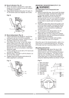
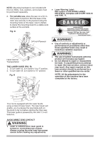
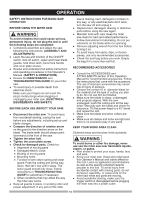
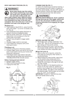
BEVEL CUT (FIG. V) 1. When a bevel cut is required, loosen the bevel lock handle (1). 2. Tilt the cutting head to the desired angle as shown on the bevel scale (2). The blade can be positioned at any angle, from a 90° straight cut (0° on the scale) to a 45° left bevel. 3. Tighten the bevel lock handle (1) to lock the cutting head in position. 4. Positive stops are provided at 0° and 45°. Fig. X Hold-Down Clamp Fig. V Workpiece 1 2 COMPOUND CUT (FIG. W) A compound cut is the combination of a miter and a bevel cut simultaneously. 1. Loosen the bevel lock handle (1) and position the cutting head at the desired bevel position. Lock the bevel lock handle. 2. Loosen the miter table lock handle (2). Press down the positive stop locking lever (3) and position the table at the desired angle. Release the positive stop locking lever and lock the miter handle. Fig. W CUTTING BASE MOLDING (FIG. Y) Base moldings and many other moldings can be cut on a compound miter saw. The setup of the saw depends on molding characteristics and application, as shown. Perform practice cuts on scrap material to achieve best results: 1. Always make sure moldings rest firmly against fence and table. Use hold-down or C-clamps, whenever possible, and place tape on the area being clamped to avoid marks. 2. Reduce splintering by taping the cut area prior to making cut. Mark cut line directly on the tape. 3. Splintering typically happens due to wrong blade application and thinness of the material. Fig. Y F e Workpiece n c e F e Workpiece n c e Miter Saw Table Miter Saw Table miter at 450, bevel at 00 miter at 00, bevel at 450 1 3 2 CUTTING BOWED MATERIAL (FIG. X) A bowed workpiece must be positioned against the fence and secured with a clamping device as shown before cutting. Do not position workpiece incorrectly or try to cut the workpiece without the support of the fence. This will cause the blade to bind and could result in personal injury. NOTE: Always perform a dry run cut so you can determine if the operation being attempted is possible before power is applied to the saw. CUTTING CROWN MOLDING (FIG. Z, AA ) Your compound miter saw is suited for the difficult task of cutting crown molding. To fit properly, crown molding must be compoundmiterd with extreme accuracy. The two surfaces on a piece of crown molding that fit flat against the ceiling and wall are at angles that, when added together equal exactly 90°. Most crown molding has a top rear angle (the section that fits flat against the ceiling) of 52° and a bottom rear angle (the section that fits flat against the wall) of 38°. 21
-
 1
1 -
2
-
3
-
4
-
5
-
6
-
7
-
8
-
9
-
10
-
11
-
12
-
13
-
14
-
15
-
 16
16 -
 17
17 -
 18
18 -
 19
19 -
 20
20 -
 21
21 -
 22
22 -
 23
23 -
 24
24 -
 25
25 -
 26
26 -
27
-
28
-
29
 |
 |
