Creative SB0350 Hardware Programming Guide - Page 65
Creative SB0350 Manual
 |
View all Creative SB0350 manuals
Add to My Manuals
Save this manual to your list of manuals |
Page 65 highlights
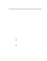
Mixer Chip Programming 4-7 Stereo Digitized Sound Output Switch There is a switch on CT1345 to toggle digitized sound output data between the left and right DAC channels. The first digitized sound data byte will be directed to the left channel. It must be switched "On" for stereo digitized sound output. Register Functions The following notations are used to describe the detailed register map of CT1345: „ „ ".L" stands for left channel and ".R" stands for right channel. "0xRR" represents the mixer register number in hexadecimal. If "0xRR:D,D" is used, this means only the particular bit D is used to control the mixer element (comma is used to separate the bits if more than one bit is used to control the element). The entire register is dedicated to the mixer element if D is omitted. The grayed areas of the table represent reserved bits. D6 Voice volume.L Input Filter Output Filter Master volume.L MIDI volume.L CD volume.L Line volume.L Master volume.R MIDI volume.R CD volume.R Line volume.R Low-Pass Filter „ Index 0x00 0x04 0x0A 0x0C 0x0E 0x22 0x26 0x28 0x2E D7 D5 D4 D3 D2 Voice volume.R D1 D0 Reset Mixer Mic volume Input Source Stereo Switch Figure 4-2: Register Map of CT1345 Mixer The function of each register is discussed below: Register 0x00 (Reset Mixer) Write any 8-bit value to this register to reset the mixer. After a reset, all the registers will be restored to their default values.
-
 1
1 -
2
-
3
-
4
-
5
-
6
-
7
-
8
-
9
-
10
-
11
-
12
-
13
-
14
-
15
-
16
-
17
-
18
-
19
-
20
-
21
-
22
-
23
-
24
-
25
-
26
-
27
-
28
-
29
-
30
-
31
-
32
-
33
-
34
-
35
-
36
-
37
-
38
-
39
-
40
-
41
-
42
-
43
-
44
-
45
-
46
-
47
-
48
-
49
-
50
-
51
-
52
-
53
-
54
-
55
-
56
-
57
-
58
-
59
-
 60
60 -
 61
61 -
 62
62 -
 63
63 -
 64
64 -
 65
65 -
 66
66 -
 67
67 -
 68
68 -
 69
69 -
 70
70 -
71
-
72
-
73
-
74
-
75
-
76
-
77
-
78
-
79
-
80
-
81
-
82
-
83
-
84
-
85
-
86
-
87
-
88
-
89
-
90
-
91
-
92
-
93
-
94
-
95
-
96
-
97
-
98
-
99
-
100
-
101
-
102
-
103
-
104
-
105
-
106
-
107
-
108
-
109
-
110
-
111
-
112
-
113
-
114
-
115
-
116
-
117
-
118
-
119
-
120
-
121
-
122
-
123
-
124
-
125
-
126
-
127
-
128
-
129
-
130
-
131
-
132
-
133
-
134
-
135
-
136
-
137
-
138
-
139
-
140
-
141
 |
 |