Cub Cadet 3X 28 3X 26034 Operator's Manual - Page 13
Adjustments
 |
View all Cub Cadet 3X 28 manuals
Add to My Manuals
Save this manual to your list of manuals |
Page 13 highlights
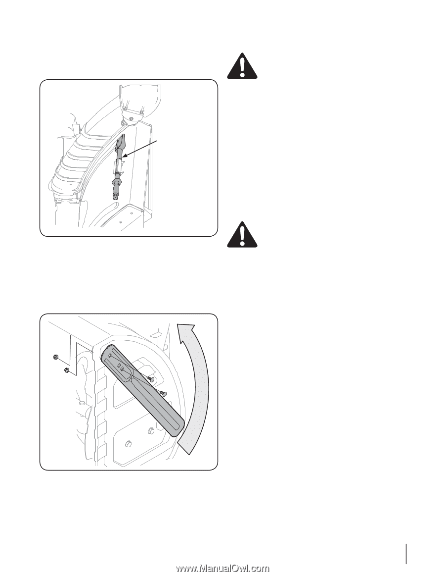
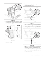
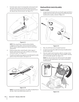
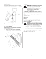
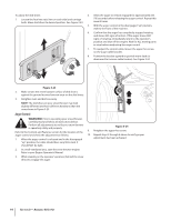
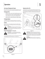
Chute Clean-Out Tool The chute clean-out tool is fastened to the top of the auger housing with a mounting clip and a cable tie at the factory. Cut the cable tie before operating the snow thrower. See Figure 3-21. Chute Clean-Out Tool Figure 3-21 Drift Cutters (If Equipped) The snow thrower drift cutters are mounted inverted at the factory for shipping purposes. 1. Remove the four flange nuts (two on each side) and carriage bolts. Place drift cutter in upright position and re-secure. See Figure 3-22. Tire Pressure WARNING! Under any circumstance do not exceed manufacturer's recommended psi. Equal tire pressure should be maintained at all times. Excessive pressure when seating beads may cause tire/rim assembly to burst with force sufficient to cause serious injury. Refer to sidewall of tire for recommended pressure. The tires are over-inflated for shipping purposes. Check the tire pressure before operating the snow thrower. Refer to the tire side wall for tire manufacturer's recommended psi and deflate (or inflate) the tires as necessary. NOTE: Equal tire pressure is to be maintained at all times for performance purposes. Adjustments Skid Shoes The snow thrower skid shoes are adjusted at the factory for shipping purposes. Adjust them downward, if desired, prior to operating the snow thrower. CAUTION: It is not recommended that you operate this snow thrower on gravel as it can easily pick up and throw loose gravel, causing personal injury or damage to the snow thrower and surrounding property. • For close snow removal on a smooth surface, raise skid shoes higher on the auger housing. • Use a middle or lower position when the area to be cleared is uneven, such as a gravel driveway NOTE: If you choose to operate the snow thrower on a gravel surface, keep the skid shoes in position for maximum clearance between the ground and the shave plate. Figure 3-22 Section 3 - Assembly & Set-Up 13
-
 1
1 -
2
-
3
-
4
-
5
-
6
-
7
-
 8
8 -
 9
9 -
 10
10 -
 11
11 -
 12
12 -
 13
13 -
 14
14 -
 15
15 -
 16
16 -
 17
17 -
 18
18 -
19
-
20
-
21
-
22
-
23
-
24
-
25
-
26
-
27
-
28
 |
 |