D-Link DCS-45 User Manual
D-Link DCS-45 Manual
 |
UPC - 790069285189
View all D-Link DCS-45 manuals
Add to My Manuals
Save this manual to your list of manuals |
D-Link DCS-45 manual content summary:
- D-Link DCS-45 | User Manual - Page 1
Model No.: DCS-45 User's Manual Ⅰ. Introduction The DCS-45 camera housing is built using die-cast aluminum, powder coated and stove finished. The design and manufacture is adapted to the highest technical standard with IP 66 level of environmental protection. The housing is provided with an - D-Link DCS-45 | User Manual - Page 2
Ⅲ. Fitting instructions for camera 5 1 Fig.3 4 (A) 23 (C) 1 Camera mounting platform 2 Terminal block assembly 3 Cable conduits PGB13.5 x 2 4 Captive retainning 1/4" Screws x 3 5 Ground wire (H) (G) (B) (C) (F) (E) (J) (D) (G) (I) 1. Unscrew the 3 captive retaining screws (C) and remove - D-Link DCS-45 | User Manual - Page 3
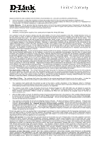
price paid. Any repair or replacement will be rendered by D-Link at an Authorized D-Link Service a Case ID Number from D-Link Technical Support at 1-877-453-5465, who ID Number at https://rma.dlink.com/. After an RMA include any manuals or accessories in the shipping package. D-Link will only - D-Link DCS-45 | User Manual - Page 4
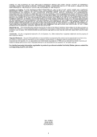
LINK FOR WARRANTY SERVICE) RESULTING FROM THE USE OF THE PRODUCT, RELATING TO WARRANTY SERVICE, OR ARISING OUT OF ANY BREACH OF THIS LIMITED WARRANTY, EVEN IF D-LINK CONFORMING PRODUCT. THE MAXIMUM LIABILITY OF D-LINK UNDER THIS WARRANTY IS LIMITED TO THE PURCHASE PRICE OF THE PRODUCT COVERED BY THE
-
 1
1 -
 2
2 -
 3
3 -
 4
4
 |
 |
1
Model No.:
DCS-45
User’s Manual
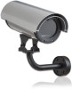
Ⅰ.
Introduction
The DCS-45 camera housing is built using die-cast aluminum, powder coated and stove
finished. The design and manufacture is adapted to the highest technical standard with IP
66 level of environmental protection. The housing is provided with an adjustable semi-cable-
managed mounting bracket.
(D)
(E)
(F)
(K)
(G)
Fig.1
(B)
90
°
90
°
78
65
(H)
Fig.2
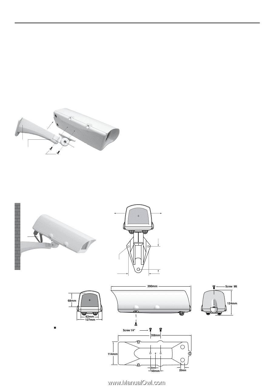
Inner space for camera mount
W90 x H70 x L230mm
1. Use the rear section of the
mounting bracket
(D)
as a template for marking the position of the
mounting holes
(H). Remove and drill the holes
accordingly.
2. Attach the mounting bracket arm to the wall using
the rawlplugs and screws provided.
3. Attach the
main housing enclosure
(K) to the
mounting bracket with two of 1/4” x 14.7 mm
trilobular screws
(F) provided.
4. Release
screw
(E) on the mounting bracket to pan
the housing and then release
screw
(G) to tilt the
housing. Position the housing as required for the
correct camera coverage and then securely tighten
the screws.
5. Feed cables through the
cover plate
(B) of the
mounting bracket from the wall, or by using cable
conduits.
Ⅱ.
Mounting configuration of
DCS-45