D-Link DCS-60 User Manual
D-Link DCS-60 Manual
 |
UPC - 790069284601
View all D-Link DCS-60 manuals
Add to My Manuals
Save this manual to your list of manuals |
D-Link DCS-60 manual content summary:
- D-Link DCS-60 | User Manual - Page 1
Model No.: DCS-60 User's Manual Ⅰ. Introduction The DCS-60 Camera Housing is constructed from die-cast Managed Bracket (the concealed cable channel inside the mounting bracket). Ⅱ. Mounting configuration of DCS-60 Fig.1 1. Use the rear section of the Mounting Bracket (D) as a template for - D-Link DCS-60 | User Manual - Page 2
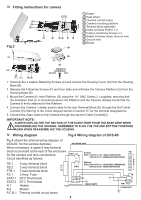
Ⅲ. Fitting instructions for camera Fig.3 (H) 1 Heater 2 Heat DCS-60 for the window demister. When necessary, a spare 6 way terminal block is provided at the rear of the enclosure for the camera and lens connections. Circuit identified as follows: TURN OFF AT 28℃ RISING TEMPERATURE TURN ON AT 18 - D-Link DCS-60 | User Manual - Page 3
the original owner or to refund the actual purchase price paid. Any repair or replacement will be rendered by D-Link at an Authorized D-Link Service Office. The replacement hardware need not be new or have an identical make, model or part. D-Link may, at its option, replace the defective Hardware or - D-Link DCS-60 | User Manual - Page 4
pursuant to part 15 of the FCC Rules. These limits are designed to provide reasonable protection against harmful interference in a residential installation. This equipment generates, uses, and can radiate radio frequency energy and, if not installed and used in accordance with the instructions, may
-
 1
1 -
 2
2 -
 3
3 -
 4
4
 |
 |
1
Model No.:
DCS-60
User’s Manual
Ⅰ.
Introduction
The DCS-60 Camera Housing is constructed from die-cast aluminium and is powder coated
and stove finished.The design and manufacture is to the highest technical standard with
environmental protection to level IP 67.
The Housing is supplied complete with an adjustable
Fully-Cable-Managed Bracket (the concealed cable channel inside the mounting bracket).
Ⅱ.
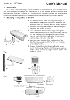
Mounting configuration of
DCS-60
Fig.1
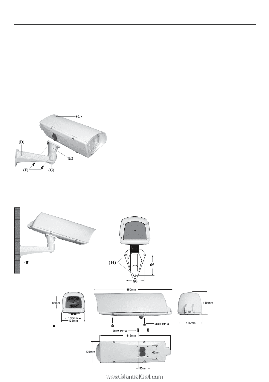
Fig.2
Inner space for camera mount
W105 x H80 x L250mm
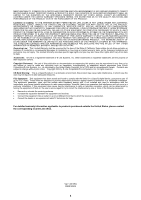
1. Use the rear section of the Mounting Bracket (D) as
a template for marking the position on the wall of the
Mounting Holes (H). Remove & drill to pattern required.
2. Attach the Mounting Bracket arm to the wall using the
rawlplugs and screws provided.
3. Feed cables from the main Housing (C) through the
hole of the Mounting Plate (E) on the Mounting Bracket
(D), and then feed the cable again to the concealed
channel inside the Mounting Bracket throughout the
wall outlet (A) or bracket outlet (B).
4. Attach the main Housing (C) to the Mounting Plate
(E) of the Bracket with 4 of 1/4” x 14.7 mm Trilobular
screws (F) provided.
5. Release Screw (G) on the Mounting Bracket to pan
and tilt the Housing . Position the Housing as required
for the correct Camera coverage, and then tighten both
screws to secure.