D-Link DCS-60 User Manual - Page 1
D-Link DCS-60 Manual
 |
UPC - 790069284601
View all D-Link DCS-60 manuals
Add to My Manuals
Save this manual to your list of manuals |
Page 1 highlights
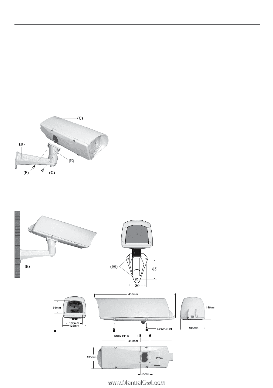
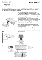
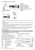
Model No.: DCS-60 User's Manual Ⅰ. Introduction The DCS-60 Camera Housing is constructed from die-cast aluminium and is powder coated and stove finished.The design and manufacture is to the highest technical standard with environmental protection to level IP 67. The Housing is supplied complete with an adjustable Fully-Cable-Managed Bracket (the concealed cable channel inside the mounting bracket). Ⅱ. Mounting configuration of DCS-60 Fig.1 1. Use the rear section of the Mounting Bracket (D) as a template for marking the position on the wall of the Mounting Holes (H). Remove & drill to pattern required. 2. Attach the Mounting Bracket arm to the wall using the rawlplugs and screws provided. 3. Feed cables from the main Housing (C) through the hole of the Mounting Plate (E) on the Mounting Bracket (D), and then feed the cable again to the concealed channel inside the Mounting Bracket throughout the wall outlet (A) or bracket outlet (B). 4. Attach the main Housing (C) to the Mounting Plate (E) of the Bracket with 4 of 1/4" x 14.7 mm Trilobular screws (F) provided. 5. Release Screw (G) on the Mounting Bracket to pan and tilt the Housing . Position the Housing as required for the correct Camera coverage, and then tighten both screws to secure. Fig.2 Inner space for camera mount W105 x H80 x L250mm 1
-
 1
1 -
 2
2 -
 3
3 -
 4
4
 |
 |