D-Link DCS-60 User Manual - Page 2
Fitting instructions for camera, Fig.3, Wiring diagram, Fig.4 Wiring diagram of DCS-60 - 18
 |
UPC - 790069284601
View all D-Link DCS-60 manuals
Add to My Manuals
Save this manual to your list of manuals |
Page 2 highlights
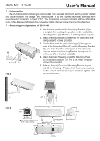
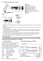
Ⅲ. Fitting instructions for camera Fig.3 (H) 1 Heater 2 Heat shield 3 Thermal control board 4 Camera mounting platform 5 Terminal block assembly 6 Cable conduits PGB11 x 2 7 Captive retainning Screws x 4 8 Heater & blower wires, Ground wire 9 Ground wire 10 Blower (G) (F) (J) (G) (I) 1. Unscrew the 3 captive Retaining Screws (C) and remove the Housing Cover (A) from the Housing Base (B). 2. Release the 4 Keyhole Screws (F) and then slide and withdraw the Camera Platform (G) from the Housing Base (B). 3. Mount the Camera (H) onto Platform (G) using the 1/4" UNC Screw ( I ) supplied, ensuring that the Insulation Pad (J) is mounted between the Platform and the Camera. Always check that the Camera is firmly attached to the Platform. 4. Connect the Camera / Heater power cable to the rear Terminal Block (E) through the first Cable Conduit (D) referring to the circuit diagram shown in section IV. for the terminal designations. 5. Connect the video cable to the Camera through the second Cable Conduit(D). IMPORTANT NOTE: ALWAYS UNPLUG THE TOP SECTION OF THE EARTH WIRE FROM THE BASE WIRE WHEN DISASSEMBLING THE HOUSING. REMEMBER TO PLUG THE TOP AND BOTTOM TOGETHER AGAIN WHEN REASSEMBLING THE HOUSING. Ⅳ. Wiring diagram Fig.4 Wiring diagram of DCS-60 Fig.4 shows the internal wiring diagram of DCS-60 for the window demister. When necessary, a spare 6 way terminal block is provided at the rear of the enclosure for the camera and lens connections. Circuit identified as follows: TURN OFF AT 28℃ RISING TEMPERATURE TURN ON AT 18℃ DECREASING TEMPERATURE TB.1 6 way terminal block TB.2 3 way terminal block FTB.1 Fused terminal block FS.1 3 Amp. Fuse STAT.1 28℃ Thermostat STAT.2 35℃ Thermostat H.1 Heater B.2 Blower P.C.B.1 Thermal control circuit board 2
-
 1
1 -
 2
2 -
 3
3 -
 4
4
 |
 |
