D-Link DGS-1008D Product Manual - Page 11
LED Indicators - dgs switch
 |
UPC - 790069252730
View all D-Link DGS-1008D manuals
Add to My Manuals
Save this manual to your list of manuals |
Page 11 highlights
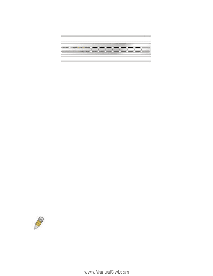
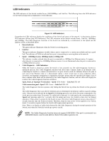
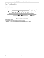
D-Link DGS -1008D Unmanaged Gigabit Ethernet Switch LED Indicators The LED indicators of the Switch include Power, 100/1000Mbps, and Link/Act. The following shows the LED indicators for the Switch along with an explanation of each indicator. Figure 1-2. LED Indicators Comprehensive LED indicators display the conditions of the Switch and status of the network. A description of these LED indicators follows (see LED Indicators). The LED indicators of the Switch include Power, Link/Act, 1000Mbps, and 100Mbps. The Cable Diagnostic functions of the Switch are indicated by a combination of the Speed and the Link/Act LEDs, as described below. § Power Indicator This green indicator illuminates when the Switch is receiving power. § Link/Act This green indicator illuminates steadily when a port is connected to a station successfully and has a good link. The indicator will blink to indicate that a port is transmitting or receiving data on the network. § Speed − 1000Mbps/Green; 100Mbps/Amber; 10Mbps/Off This indicator is amber -colored when the port is connected to a 100Mbps Fast Ethernet station. It is green when the port is connected to a 1000Mbps Ethernet station. It is not illuminated when the port is connected to a 10Mbps Ethernet station. § Cable Diagnostic − LED Indications When the Switch is booted up (when the Switch is first powered on), the Cable Diagnostic function is initialized and run. The Cable Diagnostic function will detect three common faults in an Ethernet cable connecting the Switch to a remote network device: an open circuit (a lack of continuity between the pins at each end of the Ethernet cable or a disconnected cable), a short circuit (two or more conductors shortcircuited), and improper termination (a termination resistance greater than the specified 100 ohms). Any of these common cable faults will be detected by the Cable Diagnostic function, and the LEDs will display the results of the Cable Diagnostic function as follows: Open, Short, or Improper Termination − Speed LED: Amber − Link/Act LED: Off Cable connection good − Speed LED: Green − Link/Act LED: Off The Cable Diagnostic function operates only during the Switch boot up (when the Switch is first powered on). The Cable Diagnostic first scans the five Ethernet ports to determine if the Ethernet cable is in good working order. This process is indicated by the Speed LED blinking green for each of the five ports, sequentially. The initial port scan takes about 10 seconds. If a cable fault is detected, it is indicated by the corresponding port's Speed LED glowing amber for 5 seconds, after the initial port scan. The Switch is then reset for normal operation. It takes about 2 seconds for the Switch to reset. The entire Cable Diagnostic process takes about 17 seconds from the time the Switch is booted. Therefore, from the time power is first applied to the Switch, about 17 seconds is required before the Switch will begin normal operation. Note: There is no display of cable faults detected by the Cable Diagnostic during the normal operation of the Switch, only when the Switch is booted up or power-cycled. NOTE: The Cable Diagnostic function does not support 10M/100M. If the port is connected to a 10M/100M device, see the Link LED to check if the cable is good or not. 4 4
-
 1
1 -
2
-
3
-
4
-
5
-
 6
6 -
 7
7 -
 8
8 -
 9
9 -
 10
10 -
 11
11 -
 12
12 -
 13
13 -
 14
14 -
 15
15 -
 16
16 -
17
-
18
-
19
-
20
-
21
-
22
-
23
-
24
-
25
-
26
-
27
-
28
 |
 |