D-Link DGS-1008D Product Manual - Page 14
Mounting the Switch on a Wall, Attaching the Rubber Feet - dgs hook up
 |
UPC - 790069252730
View all D-Link DGS-1008D manuals
Add to My Manuals
Save this manual to your list of manuals |
Page 14 highlights
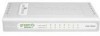
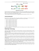
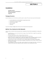
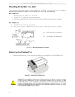
D-Link DGS -1008D Unmanaged Gigabit Ethernet Switch Mounting the Switch on a Wall The DGS-1008D can be mounted on a wall. Two mounting slots are provided on the bottom of the Switch for this purpose. Make sure that the front panel is exposed in order to view the LEDs. Refer to the illustration below: A.) Cement wall 1. Mount the nylon screw anchors into a cement wall. 2. Drive the T3 x 15L screws into the nylon screw anchors. 3. Hook the mounting holes at the back of the switch onto the screws. The wall-mount process is complete. B.) Wooden wall 1. Insert the T3 x 15 L screws into the wood wall. 2. Hook the mounting holes at the back of the switch onto the screws. The wall-mount process is complete. (1) 3/4 inch minimu m for a wooden wall. (2) 3 inch minimum for a cement wall. Figure 2 - 1. Mounting the Switch to a Wall Attaching the Rubber Feet § Use the rubber feet provided. Position and apply the rubber feet to the underside of the DGS-1008D Switch. Figure 2 -2. Attaching the Rubber Feet CAUTION: Do not place any device on top of Switch, or place the Switch on top of any device or object that will block the free flow of air through the ventilation slots on the sides, top, and bottom of the Switch's case. In addition, care should be taken not to locate the Switch next to, on top of, or underneath any device that generates a significant amount of heat. For the Switch to perform at its optimal level, the Switch must have adequate ventilation to prevent the Switch from overheating and becoming damaged. 7 7
-
 1
1 -
2
-
3
-
4
-
5
-
6
-
7
-
8
-
 9
9 -
 10
10 -
 11
11 -
 12
12 -
 13
13 -
 14
14 -
 15
15 -
 16
16 -
 17
17 -
 18
18 -
 19
19 -
20
-
21
-
22
-
23
-
24
-
25
-
26
-
27
-
28
 |
 |