D-Link DGS-3620-52P Hardware Installation Guide - Page 14
LEDs for Power, Console,RPS, SD card slot, PoE, MGMT and Link/Act/Speed for each port
 |
View all D-Link DGS-3620-52P manuals
Add to My Manuals
Save this manual to your list of manuals |
Page 14 highlights
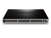
xStack® DGS-3620 Series Layer 3 Managed Stackable Gigabit Switch Hardware Installation Guide Figure 1-7 Front panel view of a DGS-3620-52P Switch Forty-eight 10/100/1000 PoE+ Base-T Four SFP+ ports LEDs for Power, Console,RPS, SD card slot, PoE, MGMT and Link/Act/Speed for each port NOTE: The alarm PIN's 1,2 and 3 works under 60V while pins 4,5,6, and 7 works under 3V CAUTION: The alarm port on the DGS-3620 Series is provided to trigger external events that may affect the switch. These could be fan or temperature failures. Connect the alarm input pins on the switch to the alarm output terminals on other devices. Connect the alarm output pins on external devices to alarm input pins on the switch. 14
-
 1
1 -
2
-
3
-
4
-
5
-
6
-
7
-
8
-
 9
9 -
 10
10 -
 11
11 -
 12
12 -
 13
13 -
 14
14 -
 15
15 -
 16
16 -
 17
17 -
 18
18 -
 19
19 -
20
-
21
-
22
-
23
-
24
-
25
-
26
-
27
-
28
-
29
-
30
-
31
-
32
-
33
-
34
-
35
-
36
-
37
-
38
-
39
-
40
-
41
-
42
-
43
-
44
-
45
-
46
-
47
-
48
-
49
-
50
-
51
-
52
-
53
-
54
-
55
-
56
-
57
-
58
-
59
-
60
-
61
-
62
-
63
-
64
-
65
-
66
-
67
-
68
 |
 |

xStack
®
DGS-3620 Series Layer 3 Managed Stackable Gigabit Switch Hardware Installation Guide
14
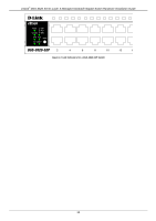
Figure 1
–
7 Front panel view of a DGS-3620-52P Switch
Forty-eight 10/100/1000 PoE+ Base-T
Four SFP+ ports
LEDs for Power, Console,RPS, SD card slot, PoE, MGMT and Link/Act/Speed for each port
NOTE:
The alarm PIN’s 1,2 and
3 works under 60V while pins 4,5,6, and 7 works under 3V
CAUTION:
The alarm port on the DGS-3620 Series is provided to trigger external events that may affect
the switch. These could be fan or temperature failures.
Connect the alarm input pins on the switch to the alarm output terminals on other devices.
Connect the alarm output pins on external devices to alarm input pins on the switch.