D-Link DSN-2100-10 Hardware Reference Guide for DSN-2100-10 Valid for fir
D-Link DSN-2100-10 - xStack Storage Area Network Array Hard Drive Manual
 |
UPC - 790069310638
View all D-Link DSN-2100-10 manuals
Add to My Manuals
Save this manual to your list of manuals |
D-Link DSN-2100-10 manual content summary:
- D-Link DSN-2100-10 | Hardware Reference Guide for DSN-2100-10
Valid for fir - Page 1
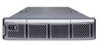
xStack Storage TM D-Link xStack Storage iSCSI SAN Array Managed SAN Solution DSN-2100 Hardware Reference Guide Version 1.0 - D-Link DSN-2100-10 | Hardware Reference Guide for DSN-2100-10
Valid for fir - Page 2
City, California. UNIX® is a registered trademark of The Open Group. All other brand or product names are or may be trademarks or service marks, and are used to identify products or services, of their respective owners. D-Link Systems, Inc. 17595 Mount Herrmann Street Fountain Valley, CA 92708 ii - D-Link DSN-2100-10 | Hardware Reference Guide for DSN-2100-10
Valid for fir - Page 3
should you need to replace it, consult your service documentation. Do not dispose of the battery along are the safety agency certifications that the xStack Storage enclosure has met: CSA 60950-1 UL Link Systems, Inc. for any export compliance questions. DSN-2100 Hardware Reference Guide iii - D-Link DSN-2100-10 | Hardware Reference Guide for DSN-2100-10
Valid for fir - Page 4
Document Revision Level Revision Date Version 1.0 October 10, 2008 Notes iv - D-Link DSN-2100-10 | Hardware Reference Guide for DSN-2100-10
Valid for fir - Page 5
with installing the xStack Storage system from DLink. This document assumes Link. xStack Storage Management Center Software User's Guide. This guide provides the information needed to configure and manage storage on the xStack Storage system using the xStack graphical user interface. DSN-2100 - D-Link DSN-2100-10 | Hardware Reference Guide for DSN-2100-10
Valid for fir - Page 6
to Friday 8:00am - 5:00pm PST/PDT D-Link Technical Support over the Internet: http://support.dlink.com Tech Support for customers within Canada: D-Link Technical Support over the Telephone Please see our support site for current number: http://support.dlink.ca Monday to Friday 7:30am to 9:00pm - D-Link DSN-2100-10 | Hardware Reference Guide for DSN-2100-10
Valid for fir - Page 7
22 3.7 Powering-on the DSN-2100 Storage System 22 Appendix A Replacing and Upgrading FRUs 23 A.1 Installing the Battery Pack 23 A.2 Installing Memory 26 A.3 Installing or Replacing SATA Drives 28 A.4 Replacing a Fan 33 A.5 Replacing a Power Supply 35 DSN-2100 Hardware Reference Guide vii - D-Link DSN-2100-10 | Hardware Reference Guide for DSN-2100-10
Valid for fir - Page 8
This Page Left Intentionally Blank viii Contents - D-Link DSN-2100-10 | Hardware Reference Guide for DSN-2100-10
Valid for fir - Page 9
D-Link Support Web site: support.dlink.com 1.1 Model The DSN-2100 storage system is presently available as a single model. Table 1-1. DSN-2100 Model Number Model DSN-2100-10 Host Network Interface Four 1GbE data ports Maximum Number of Internal SATA Drives 8 DSN-2100 Hardware Reference Guide - D-Link DSN-2100-10 | Hardware Reference Guide for DSN-2100-10
Valid for fir - Page 10
pack ensures that a charged battery is on hand to preserve buffer cache contents if a power failure occurs. Contents are backed up for approximately 72 hours. 1.3 System Overview Figure 1-1 shows a typical DSN-2100 storage system configuration in a Storage Area Network (SAN). The SAN shown is an - D-Link DSN-2100-10 | Hardware Reference Guide for DSN-2100-10
Valid for fir - Page 11
2 DSN-2100 Layout This chapter describes the hardware components on the DSN-2100 storage system. The topics covered in this chapter are: Section 2.1, Front Panel Components Section 2.2, Rear Panel Components Section 2.3, Side and Bottom Panel Components DSN-2100 Hardware Reference Guide 11 - D-Link DSN-2100-10 | Hardware Reference Guide for DSN-2100-10
Valid for fir - Page 12
2.1 Front Panel Components The front of the DSN-2100 storage system has the following components: Power LED - shows the DSN-2100 power on status. (see Figure 2-1 and Table 2-1) Boot and Fault LED - shows whether the DSN-2100 is ready for operation or encountered a fault condition. (see Figure - D-Link DSN-2100-10 | Hardware Reference Guide for DSN-2100-10
Valid for fir - Page 13
the xStack Storage Array, please be sure these vents are not blocked. A fully loaded array with all drive bays filled can generate a significant amount of heat. Please be sure the cover is in place to provide the forced air flow required for proper cooling. DSN-2100 Hardware Reference Guide 13 - D-Link DSN-2100-10 | Hardware Reference Guide for DSN-2100-10
Valid for fir - Page 14
2-3). Power - two power receptacles are located on the right side of the rear panel. Power supply alarm silence button - located on the rear of the power supply. (see Figure 2-2) Power Supply Alarm Silence Button Figure 2-2 Back View of the DSN-2100 Storage System 14 Chapter 2 DSN-2100 Layout - D-Link DSN-2100-10 | Hardware Reference Guide for DSN-2100-10
Valid for fir - Page 15
Switch Power Reset Table 2-3 Rear Panel Switches Description Applies power to the DSN-2100 storage system. Pressing this switch for longer than 3 seconds removes power from the DSN-2100 storage system and turns it off. Resets the DSN-2100 storage system. DSN-2100 Hardware Reference Guide 15 - D-Link DSN-2100-10 | Hardware Reference Guide for DSN-2100-10
Valid for fir - Page 16
OFF Yellow ON Description Link is operational. Data is being transmitted or received on the RJ-45 port. Connection has been established at 10 Mbps. Connection has been established at 100 Mbps. 2.3 Side and Bottom Panel Components The left and right sides of the DSN-2100 storage system enclosure - D-Link DSN-2100-10 | Hardware Reference Guide for DSN-2100-10
Valid for fir - Page 17
the DSN-2100 Storage System Section 3.3, Items Supplied by the User Section 3.4, Connecting to the iSCSI Data Ports Section 3.5, Connecting to the Management Port Section 3.6, Connecting the Power Cords Section 3.7, Powering-on the DSN-2100 Storage System DSN-2100 Hardware Reference Guide - D-Link DSN-2100-10 | Hardware Reference Guide for DSN-2100-10
Valid for fir - Page 18
through the DSN2100 ventilation slots. 3.1.2 Desktop, Floor or Shelf Installation The DSN-2100 storage system can be mounted on a desktop or shelf. Observe the following considerations for desktop or shelf installations. Select a sturdy, level surface that can support the DSN-2100 storage system - D-Link DSN-2100-10 | Hardware Reference Guide for DSN-2100-10
Valid for fir - Page 19
the DSN-2100 enclosure. The air flow clearances specified in this guide must be maintained within the rack. The AC supply circuit for rack-mounted equipment must be capable of supplying the total current specified on all the labels of the rack-mounted equipment. All AC power supply connections - D-Link DSN-2100-10 | Hardware Reference Guide for DSN-2100-10
Valid for fir - Page 20
. If you want to use the DSN-2100 storage system's Link Aggregation feature, the switch must support LAGs. An IP address for each DSN-2100 storage system host connection RJ-45 data port that will connect to your SAN. An Ethernet cable for each DSN-2100 storage system host connection RJ-45 data - D-Link DSN-2100-10 | Hardware Reference Guide for DSN-2100-10
Valid for fir - Page 21
DSN-2100 data ports. 3.4.1 Connecting to the DSN-2100 Host Network Connection Ports The DSN-2100 storage system has four RJ-45 data ports. These ports connect to your SAN end of the cable into the DSN-2100 storage system Mgmt 10/100 port. This port is located to DSN-2100 Hardware Reference Guide 21 - D-Link DSN-2100-10 | Hardware Reference Guide for DSN-2100-10
Valid for fir - Page 22
-on Process by... Wait five minutes after powering-on the DSN-2100 storage system. The LED turns green when the startup process completes. If the LED turns red, reboot the DSN-2100 storage system. If the problem persists, contact Technical Support. The message RCP sequence complete appears on the - D-Link DSN-2100-10 | Hardware Reference Guide for DSN-2100-10
Valid for fir - Page 23
your xStack Storage SAN Array, follow these steps: 1. Hold the battery as shown to align the fastener pad. Make sure the battery cable and connector is located nearest to the battery socket J35 on the controller (see Figure A-1 ). Figure A-1 Aligning the Battery DSN-2100 Hardware Reference Guide - D-Link DSN-2100-10 | Hardware Reference Guide for DSN-2100-10
Valid for fir - Page 24
2. Press the battery down firmly as shown in Figure A-2 until you feel it lock into place. Figure A-2 Press the Battery Down Firmly Until it Locks 3. Align the battery plug with connector J35 as shown in Figure A-3 and insert it fully into the socket. Figure A-3 Align the Battery Plug with - D-Link DSN-2100-10 | Hardware Reference Guide for DSN-2100-10
Valid for fir - Page 25
4. The connector locked firmly into connector J35. Figure A-4 Battery Plug Locked in Place 5. The installed battery is shown in Figure A-5. Figure A-5 The Installed Battery DSN-2100 Hardware Reference Guide 25 - D-Link DSN-2100-10 | Hardware Reference Guide for DSN-2100-10
Valid for fir - Page 26
memory must be installed as matching pairs. Table A-1 lists the specifications for DIMMs supported by the xStack Storage Array. These memory module specifications are crucial to the operation of your SAN array. Please visit the www.dlink.com website for tested memory modules. Table A-2 shows the - D-Link DSN-2100-10 | Hardware Reference Guide for DSN-2100-10
Valid for fir - Page 27
A-1. xStack Storage Array DIMM Specifications Description SDRAMs must be JEDEC compliant and DDR333 capable, with a CAS latency of 2.5. PC2100/DDR400 speed DIMMs can be used if they support a Cache Memory 512MB 1GB 2GB 4GB Total Memory 1GB 1.5GB 2.5GB 4.5GB DSN-2100 Hardware Reference Guide 27 - D-Link DSN-2100-10 | Hardware Reference Guide for DSN-2100-10
Valid for fir - Page 28
loss of all data in a volume. A drive can be part of a volume that may or may not be redundant. Before removing a drive from an operating xStack Storage Array, make sure it is the correct one. A.3.1 Drive and Tray Removal A drive/tray assembly can be removed by pressing upwards on the green - D-Link DSN-2100-10 | Hardware Reference Guide for DSN-2100-10
Valid for fir - Page 29
lifting the piece out of the tray as shown in Figure A-9. Figure A-9 Removing the Plastic Air Dam Piece 2. Your tray should now look like Figure A-10. Figure A-10 Tray with Air Dam Removed DSN-2100 Hardware Reference Guide 29 - D-Link DSN-2100-10 | Hardware Reference Guide for DSN-2100-10
Valid for fir - Page 30
3. Place new hard drive in tray as shown in Figure A-11. Figure A-11 Place Hard Drive in Tray 4. Align the mounting holes and insert four mounting screws to hold the drive securely in the drive tray as shown in Figure A-12. Figure A-12 Secure the Hard Drive in the Drive Tray 30 Appendix A - D-Link DSN-2100-10 | Hardware Reference Guide for DSN-2100-10
Valid for fir - Page 31
you must push the tray handle inwards as shown in Figure A-15 until you hear the green locking mechanism click. Figure A-13 Drive/Tray Installation DSN-2100 Hardware Reference Guide 31 - D-Link DSN-2100-10 | Hardware Reference Guide for DSN-2100-10
Valid for fir - Page 32
Figure A-14 Press Here Until You See the Lever Move Inwards Figure A-15 Press Lever Inwards Until it Locks 32 Appendix A Replacing and Upgrading FRUs - D-Link DSN-2100-10 | Hardware Reference Guide for DSN-2100-10
Valid for fir - Page 33
A.4 Replacing a Fan The xStack Storage Array contains three user replaceable fans. They can be replaced as follows. 1. Locate the failed fan. They can , grasp it and pull the fan upwards as seen in Figure A-17. Figure A-17 Lift the Handle and Pull Upwards DSN-2100 Hardware Reference Guide 33 - D-Link DSN-2100-10 | Hardware Reference Guide for DSN-2100-10
Valid for fir - Page 34
3. Remove the fan from its socket as seen in Figure A-18. Figure A-18 Remove the Fan 4. Insert the new fan by reversing the previous steps. i.e. Insert fan into socket, press firmly downwards until it is seated and lower the handle to lock it in place. 34 Appendix A Replacing and Upgrading FRUs - D-Link DSN-2100-10 | Hardware Reference Guide for DSN-2100-10
Valid for fir - Page 35
Replacing a Power Supply The xStack Storage Array contains three user replaceable power supply modules. They can be replaced as follows. 1. Locate the failed power supply module. Left and Pull Handle 3. Remove the power supply module as shown in Figure A-21. DSN-2100 Hardware Reference Guide 35 - D-Link DSN-2100-10 | Hardware Reference Guide for DSN-2100-10
Valid for fir - Page 36
Figure A-21 Remove the Power Supply Module 4. Insert the new power supply module by reversing the previous steps. i.e. Insert the new power supply module into the bay until it seats against the rear and the lever locks. Then screw the locking bolt into place. 36 Appendix A Replacing and
-
 1
1 -
 2
2 -
 3
3 -
 4
4 -
 5
5 -
 6
6 -
 7
7 -
8
-
9
-
10
-
11
-
12
-
13
-
14
-
15
-
16
-
17
-
18
-
19
-
20
-
21
-
22
-
23
-
24
-
25
-
26
-
27
-
28
-
29
-
30
-
31
-
32
-
33
-
34
-
35
-
36
 |
 |

xStack Storage
TM
D-Link xStack Storage iSCSI SAN Array
Managed SAN Solution
DSN-2100
Hardware Reference Guide
Version 1.0