Dell Alienware Alpha R2 Alienware Steam Machine R2 Service Manual - Page 72
front-panel light board, back panel
 |
View all Dell Alienware Alpha R2 manuals
Add to My Manuals
Save this manual to your list of manuals |
Page 72 highlights
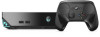
Procedure NOTE: The system board shipped in your computer may differ from the system board shown in the images below. 1 Disconnect the USB-port cable, front-panel light board cable, and powerbutton board cable from the system board. For information on the location of connectors, see "System- board components". 2 Remove the screws that secure the back panel to the chassis. 1 power-button board cable 3 USB-port cable 5 back panel 3 Turn the chassis over. 2 front-panel light board cable 4 screws (2) 72
-
 1
1 -
2
-
3
-
4
-
5
-
6
-
7
-
8
-
9
-
10
-
11
-
12
-
13
-
14
-
15
-
16
-
17
-
18
-
19
-
20
-
21
-
22
-
23
-
24
-
25
-
26
-
27
-
28
-
29
-
30
-
31
-
32
-
33
-
34
-
35
-
36
-
37
-
38
-
39
-
40
-
41
-
42
-
43
-
44
-
45
-
46
-
47
-
48
-
49
-
50
-
51
-
52
-
53
-
54
-
55
-
56
-
57
-
58
-
59
-
60
-
61
-
62
-
63
-
64
-
65
-
66
-
 67
67 -
 68
68 -
 69
69 -
 70
70 -
 71
71 -
 72
72 -
 73
73 -
 74
74 -
 75
75 -
 76
76 -
 77
77 -
78
-
79
-
80
-
81
-
82
-
83
-
84
-
85
-
86
-
87
-
88
-
89
-
90
-
91
-
92
 |
 |

Procedure
NOTE:
The system board shipped in your computer may differ from the
system board shown in the images below.
1
Disconnect the USB-port cable, front-panel light board cable, and power-
button board cable from the system board.
For information on the location of connectors, see
“System- board
components”
.
2
Remove the screws that secure the back panel to the chassis.
1
power-button board cable
2
front-panel light board
cable
3
USB-port cable
4
screws (2)
5
back panel
3
Turn the chassis over.
72