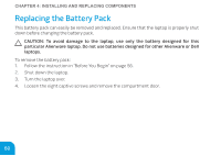
Dell Alienware M11x MOBILE MANUAL - Page 64
memory module, notch, spring locks 2, memory module connector
 |
View all Dell Alienware M11x manuals
Add to My Manuals
Save this manual to your list of manuals |
Page 64 highlights
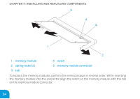
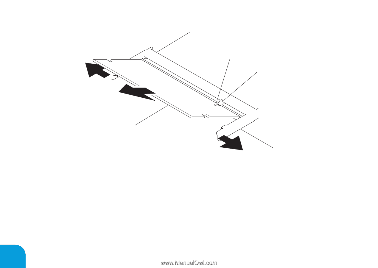
CHAPTER 4: INSTALLING AND REPLACING COMPONENTS 5 4 3 1 2 1 memory module 4 notch 2 spring locks (2) 5 memory module connector 3 tab To replace the memory modules, perform the removal steps in reverse order. While inserting the memory module into the connector align the notch on the memory module with the tab on the memory module connector. 64
-
 1
1 -
2
-
3
-
4
-
5
-
6
-
7
-
8
-
9
-
10
-
11
-
12
-
13
-
14
-
15
-
16
-
17
-
18
-
19
-
20
-
21
-
22
-
23
-
24
-
25
-
26
-
27
-
28
-
29
-
30
-
31
-
32
-
33
-
34
-
35
-
36
-
37
-
38
-
39
-
40
-
41
-
42
-
43
-
44
-
45
-
46
-
47
-
48
-
49
-
50
-
51
-
52
-
53
-
54
-
55
-
56
-
57
-
58
-
 59
59 -
 60
60 -
 61
61 -
 62
62 -
 63
63 -
 64
64 -
 65
65 -
 66
66 -
 67
67 -
 68
68 -
 69
69 -
70
-
71
-
72
-
73
-
74
-
75
-
76
-
77
-
78
-
79
-
80
-
81
-
82
-
83
-
84
-
85
-
86
-
87
-
88
-
89
-
90
-
91
-
92
-
93
-
94
-
95
-
96
-
97
-
98
-
99
-
100
 |
 |
CHAPTER 4: IN°TALLING AND REPLACING COMPONENT°
64
5
4
3
2
1
1
memory module
4
notch
2
spring locks (2)
5
memory module connector
3
tab
To replace the memory modules, perform the removal steps in reverse order. While inserting
the memory module into the connector align the notch on the memory module with the tab
on the memory module connector.