Dell Alienware M14x R2 Owner's Manual
Dell Alienware M14x R2 Manual
 |
View all Dell Alienware M14x R2 manuals
Add to My Manuals
Save this manual to your list of manuals |
Dell Alienware M14x R2 manual content summary:
- Dell Alienware M14x R2 | Owner's Manual - Page 1
Alienware M14xR2 Owner's Manual Regulatory model: P18G Regulatory type: P18G002 - Dell Alienware M14x R2 | Owner's Manual - Page 2
A CAUTION indicates potential damage to hardware or loss of data if instructions are not followed. WARNING: A WARNING indicates a potential for property of Dell Inc.; Alienware® is a trademark or registered trademark of Alienware Corporation; Microsoft®, Windows®, and the Windows start button logo - Dell Alienware M14x R2 | Owner's Manual - Page 3
11 Safety Instructions 12 Recommended Tools 12 2 After Working Inside Your Computer . . . . 13 3 Base Cover 15 Removing the Base Cover 15 Replacing the Base Cover 16 4 Battery 17 Removing the Battery 17 Replacing the Battery 18 5 Optical Drive 19 Removing the Optical Drive 19 Replacing the - Dell Alienware M14x R2 | Owner's Manual - Page 4
Hard Drive 25 Replacing the Hard Drive 27 7 Memory Module(s 29 Removing the Memory Module(s 29 Replacing the Memory Module(s 31 8 Center-Control Cover 33 Removing the Center-Control Cover 33 Replacing the Center-Control Cover 35 9 Keyboard 37 Removing the Keyboard 37 Replacing the Keyboard - Dell Alienware M14x R2 | Owner's Manual - Page 5
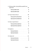
45 Removing the Mini-Card(s 45 Replacing the Mini-Card(s 47 12 Power-Button Board 49 Removing the Power-Button Board 49 Replacing the Power-Button Board 50 13 Status-Lights Board 53 Removing the Status-Lights Board 53 Replacing the Status-Lights Board 55 14 Speakers 57 Removing the - Dell Alienware M14x R2 | Owner's Manual - Page 6
Battery 70 18 Display Assembly 73 Removing the Display Assembly 73 Replacing the Display Assembly 76 19 Mini-Card Board 77 Removing the Mini-Card Board 77 Replacing the Mini-Card Board 78 20 System Board 81 Removing the System Board 81 Replacing the System Board 84 Entering the Service - Dell Alienware M14x R2 | Owner's Manual - Page 7
88 22 Thermal Cooling Assembly 89 Removing the Thermal Cooling Assembly 89 Replacing the Thermal Cooling Assembly 90 23 Processor Module 93 Removing the Processor Module 93 Replacing the Processor Module 95 24 System Setup 97 Overview 97 Entering System Setup 97 25 Flashing the BIOS 105 - Dell Alienware M14x R2 | Owner's Manual - Page 8
8 Contents - Dell Alienware M14x R2 | Owner's Manual - Page 9
files and exit all open programs. 2 Click Start and click Shut Down. Microsoft Windows shuts down and then the computer turns off. NOTE: If you are using a , see the documentation of your operating system for shut-down instructions. 3 Disconnect your computer and all attached devices from their - Dell Alienware M14x R2 | Owner's Manual - Page 10
damaging the components and cards, handle them by replace all covers, panels, and screws before connecting to the power source. CAUTION: Only a certified service technician is authorized to remove the computer cover and access any of the components inside the computer. See the safety instructions - Dell Alienware M14x R2 | Owner's Manual - Page 11
2 After Working Inside Your Computer After you complete the replacement procedures, ensure the following: • Replace all screws and ensure that no stray screws remain inside your computer • Connect any external devices, cables, cards, and any other part(s) you removed before working on your computer - Dell Alienware M14x R2 | Owner's Manual - Page 12
14 After Working Inside Your Computer - Dell Alienware M14x R2 | Owner's Manual - Page 13
3 Base Cover WARNING: Before working inside your computer, read the safety information that shipped with your computer and follow the steps in "Before You Begin" on page 11. For additional safety best practices information, see the Regulatory Compliance Homepage at dell.com/regulatory_compliance. - Dell Alienware M14x R2 | Owner's Manual - Page 14
Replacing the Base Cover Procedure 1 Align the tabs on the base cover with the slots on the computer base and slide the base cover until it snaps into place. 2 Tighten the captive screws that secure the base cover to the computer base. Postrequisites 1 Follow the instructions in "After Working - Dell Alienware M14x R2 | Owner's Manual - Page 15
4 Battery WARNING: Before working inside your computer, read the safety information safety best practices information, see the Regulatory Compliance Homepage at dell.com/regulatory_compliance. Removing the Battery Prerequisites 1 Remove the base cover. See "Removing the Base Cover" on page 15. - Dell Alienware M14x R2 | Owner's Manual - Page 16
and tighten the captive screws that secure the battery to the computer base. 2 Connect the battery cable to the connector on the system board. Postrequisites 1 Replace the base cover. See "Replacing the Base Cover" on page 16. 2 Follow the instructions in "After Working Inside Your Computer" on page - Dell Alienware M14x R2 | Owner's Manual - Page 17
, see the Regulatory Compliance Homepage at dell.com/regulatory_compliance. Removing the Optical Drive Prerequisites 1 Remove the base cover. See "Removing the Base Cover" on page 15. 2 Remove the battery. See "Removing the Battery" on page 17. Procedure 1 Lift the connector latch and use the pull - Dell Alienware M14x R2 | Owner's Manual - Page 18
2 Loosen the four captive screws that secure the optical drive to the computer base. 3 Using the pull-tab, lift the optical drive off the computer base. 5 4 3 1 2 1 optical-drive cable 3 optical drive 5 captive screws (4) 2 connector latch 4 pull tab 4 Remove the screws that secure the optical- - Dell Alienware M14x R2 | Owner's Manual - Page 19
6 Gently peel the optical-drive cable from the optical-drive bracket. 1 screws (2) 3 optical-drive cable 3 2 1 2 optical-drive cable connector Optical Drive 21 - Dell Alienware M14x R2 | Owner's Manual - Page 20
pull-tab, lift the optical-drive bracket off the optical drive. 1 2 3 1 screws (4) 3 pull tab 2 optical-drive bracket Replacing the Optical Drive Procedure 1 Place the optical-drive bracket on the optical drive and then align the screw holes on the optical-drive bracket with the screw holes on - Dell Alienware M14x R2 | Owner's Manual - Page 21
board, and press down on the connector latch to secure the cable. Postrequisites 1 Replace the battery. See "Replacing the Battery" on page 18. 2 Replace the base cover. See "Removing the Base Cover" on page 15. 3 Follow the instructions in "After Working Inside Your Computer" on page 13. Optical - Dell Alienware M14x R2 | Owner's Manual - Page 22
24 Optical Drive - Dell Alienware M14x R2 | Owner's Manual - Page 23
or Alienware, you need to install an operating system, drivers, and utilities on the new hard drive. Removing the Hard Drive Procedure 1 Remove the base cover. See "Removing the Base Cover" on page 15. 2 Remove the battery pack. See "Removing the Battery" on page 17. 3 Follow the instructions from - Dell Alienware M14x R2 | Owner's Manual - Page 24
3 Lift the hard-drive assembly off the computer base. 432 1 1 hard-drive interposer 3 pull-tab 2 captive screws (3) 4 hard-drive assembly 26 Hard Drive - Dell Alienware M14x R2 | Owner's Manual - Page 25
the safety instructions that shipped with your computer. Replacing the Hard Drive Procedure 1 Place the hard drive in the hard-drive bracket. 2 Replace the four screws that secure the hard-drive bracket to the hard drive. 3 Connect the interposer to the hard drive. 4 Place the hard-drive assembly - Dell Alienware M14x R2 | Owner's Manual - Page 26
from step 6 to step 8 in "Replacing the Optical Drive" on page 22. 2 Replace the battery. See "Replacing the Battery" on page 18. 3 Replace the base cover. See "Replacing the Base Cover" on page 16. 4 Follow the instructions in "After Working Inside Your Computer" on page 13. 28 Hard Drive - Dell Alienware M14x R2 | Owner's Manual - Page 27
at dell.com/regulatory_compliance. NOTE: Memory modules purchased from Dell or Alienware are covered under your computer warranty. Your computer has two user-accessible cover. See "Removing the Base Cover" on page 15. 2 Remove the battery. See "Removing the Battery" on page 17. Memory Module(s) 29 - Dell Alienware M14x R2 | Owner's Manual - Page 28
Procedure 1 Loosen the captive screws that secure the memory-module cover to the computer base. 2 Lift and slide the tabs on the memory-module cover out of the slots on the computer base. 2 1 1 captive screws (2) 2 memory-module cover CAUTION: To prevent damage to the memory-module connector, do - Dell Alienware M14x R2 | Owner's Manual - Page 29
4 Slide the memory module out of the memory-module connector. 1 3 1 memory-module connector 3 memory module 2 securing clips (2) Replacing the Memory Module(s) Procedure NOTE: If you need to install memory modules in both memory-module connectors, install a memory module in the lower connector - Dell Alienware M14x R2 | Owner's Manual - Page 30
that secure the memory-module cover to the computer base. Postrequisites 1 Replace the battery. See "Replacing the Battery" on page 18. 2 Replace the base cover. See "Replacing the Base Cover" on page 16. 3 Follow the instructions in "After Working Inside Your Computer" on page13. 32 Memory - Dell Alienware M14x R2 | Owner's Manual - Page 31
Homepage at dell.com/regulatory_compliance. Removing the Center-Control Cover Prerequisites 1 Remove the base cover. See "Removing the Base Cover" on page 15. 2 Remove the battery. See "Removing the Battery" on page 17. Center-Control Cover 33 - Dell Alienware M14x R2 | Owner's Manual - Page 32
Procedure 1 Remove the screws that secure the center-control cover to the computer base. 1 1 screws (3) 2 Turn the computer over and open the display as far as possible. 3 Gently pry the center-control cover and then ease the tabs on the center-control cover out of the slots on the palm-rest - Dell Alienware M14x R2 | Owner's Manual - Page 33
control cover off the palm-rest assembly. 1 1 center-control cover Replacing the Center-Control Cover Procedure 1 Align the tabs on the center- 3 Close the display and turn the computer over. 4 Replace the screws that secure the center-control cover to the computer base. Center-Control Cover 35 - Dell Alienware M14x R2 | Owner's Manual - Page 34
Postrequisites 1 Replace the battery pack. See "Replacing the Battery" on page 18. 2 Replace the base cover. See "Replacing the Base Cover" on page 16. 3 Follow the instructions in "After Working Inside Your Computer" on page13. 36 Center-Control Cover - Dell Alienware M14x R2 | Owner's Manual - Page 35
"Removing the Battery" on page 17. 3 Remove the center-control cover. See "Removing the Center-Control Cover" on page 33. Procedure 1 Remove the screws that secure the keyboard to the computer base. CAUTION: The keycaps on the keyboard are fragile, easily dislodged, and timeconsuming to replace. Be - Dell Alienware M14x R2 | Owner's Manual - Page 36
2 Carefully pry the keyboard up and slide it towards the display till the tabs on the keyboard are released from the palm-rest assembly. 3 Turn the keyboard over. 1 2 3 4 1 screws (3) 3 tabs (4) 2 keyboard 4 palm-rest assembly 38 Keyboard - Dell Alienware M14x R2 | Owner's Manual - Page 37
on the system board and disconnect the keyboard cable and keyboard-backlight cable. 5 Lift the keyboard off the palm-rest assembly. 2 1 1 keyboard cable 2 keyboard backlight cable Replacing the Keyboard Procedure 1 Slide the keyboard cable and keyboard backlight cable into the connectors on - Dell Alienware M14x R2 | Owner's Manual - Page 38
center-control cover. See "Replacing the Center-Control Cover" on page 35. 2 Replace the battery. See "Replacing the Battery" on page 18. 3 Replace the base cover. See "Replacing the Base Cover" on page 16. 4 Follow the instructions in "After Working Inside Your Computer" on page13. 40 Keyboard - Dell Alienware M14x R2 | Owner's Manual - Page 39
Homepage at dell.com/regulatory_compliance. Removing the Palm-Rest Assembly Prerequisites 1 Remove the base cover. See "Removing the Base Cover" on page 15. 2 Remove the battery. See "Removing the Battery" on page 17. Palm-Rest Assembly 41 - Dell Alienware M14x R2 | Owner's Manual - Page 40
control cover (see "Removing the Center-Control Cover" on page 33). 4 Remove the keyboard (see "Removing the Keyboard" on page 37). CAUTION: Use the pull-tabs on top of the connectors to the speakers cable and status-light board cable from the connectors on the system board. 42 Palm-Rest Assembly - Dell Alienware M14x R2 | Owner's Manual - Page 41
separate the palm-rest assembly from the computer base to avoid damage to the palm-rest assembly. 6 1 5 4 3 2 1 touch-pad cable connector 3 status-light board cable 5 palm-rest assembly 2 speakers cable 4 screws (2) 6 power-button board cable connector 8 Pry out the palm-rest assembly along - Dell Alienware M14x R2 | Owner's Manual - Page 42
status-light board cable to the connectors on the system board. 4 Slide the touch-pad cable and power-button board cable into their connectors on the system board, and press down on their connector latches to secure the cables. Postrequisites 1 Replace the keyboard. See "Replacing the Keyboard" on - Dell Alienware M14x R2 | Owner's Manual - Page 43
does not guarantee compatibility or provide support for Mini-Cards from sources other than Dell or Alienware. If you ordered a wireless mini-card with your computer, the card is already installed. NOTE: The procedure for removing and replacing the WirelessHD card (optional) is the same as Mini - Dell Alienware M14x R2 | Owner's Manual - Page 44
Procedure 1 Disconnect the antenna cables from the connectors on the mini-card. 2 Remove the screw that secures the mini-card to the system board. 1 3 1 screw 3 Mini-Card 2 2 antenna cables (2) 46 Wireless Mini-Card(s) - Dell Alienware M14x R2 | Owner's Manual - Page 45
out of the connector on the system board. Replacing the Mini-Card(s) Procedure 1 Remove the new Mini-Card from its packaging. CAUTION: Use firm and even pressure to slide the mini-card into place. If you use excessive force, you may damage the connector. CAUTION: The connectors are keyed to ensure - Dell Alienware M14x R2 | Owner's Manual - Page 46
for each mini-card supported by your computer: Connectors on the Mini-Card WLAN (2 antenna cables) Main WLAN (white triangle) Auxiliary WLAN (black triangle) Antenna Cable Color Scheme white black Postrequisites 1 Replace the battery. See "Replacing the Battery" on page 18. 2 Replace the base - Dell Alienware M14x R2 | Owner's Manual - Page 47
. See "Removing the Battery" on page 17. 3 Remove the center-control cover. See "Removing the Center-Control Cover" on page 33. 4 Remove the keyboard. See "Removing the Keyboard" on page 37. 5 Remove the palm-rest assembly. See "Removing the Palm-Rest Assembly" on page 41. Procedure 1 Gently peel - Dell Alienware M14x R2 | Owner's Manual - Page 48
1 1 power-button board 3 power-button board cable 2 screws (2) Replacing the Power-Button Board Procedure 1 Slide the power-button board cable through palm-rest assembly to place the power-button board in place. 3 Replace the screws that secure the power-button board to the palm-rest assembly - Dell Alienware M14x R2 | Owner's Manual - Page 49
. See "Replacing the Keyboard" on page 39. 3 Replace the center-control cover. See "Replacing the Center-Control Cover" on page 35. 4 Replace the battery pack. See "Replacing the Battery" on page 18. 5 Replace the base cover. See "Replacing the Base Cover" on page 16. 6 Follow the instructions in - Dell Alienware M14x R2 | Owner's Manual - Page 50
52 Power-Button Board - Dell Alienware M14x R2 | Owner's Manual - Page 51
keyboard. See "Removing the Keyboard" on page 37. 5 Remove the palm-rest assembly. See "Removing the Palm-Rest Assembly" on page 41. Procedure 1 Turn the palm-rest assembly over. 2 Note the routing of status-light board cable and remove the cable from the routing guides. NOTE: If the status-light - Dell Alienware M14x R2 | Owner's Manual - Page 52
3 Turn the palm-rest assembly over. 1 1 status-light board cable 54 Status-Lights Board - Dell Alienware M14x R2 | Owner's Manual - Page 53
Align the slot on the status-light board with the alignment post on the palm-rest assembly. 3 Replace the screw that secures the status-light board to the palm-rest assembly. 4 Turn the palm-rest assembly over. 5 Route the status-light board cable through the routing guides on the palm-rest assembly - Dell Alienware M14x R2 | Owner's Manual - Page 54
keyboard. See "Replacing the Keyboard" on page 39. 8 Replace the center-control cover. See "Replacing the Center-Control Cover" on page 35. 9 Replace the battery. See "Replacing the Battery" on page 18. 10 Replace the base cover. See "Replacing the Base Cover" on page 16. 11 Follow the instructions - Dell Alienware M14x R2 | Owner's Manual - Page 55
the Keyboard" on page 37. 5 Remove the palm-rest assembly. See "Removing the Palm-Rest Assembly" on page 41. Procedure 1 Turn the palm-rest assembly over. 2 Note the routing of speakers cable and remove the cable from the routing guides. NOTE: If the speakers cable is under the status-light board - Dell Alienware M14x R2 | Owner's Manual - Page 56
to the palm-rest assembly. 4 Lift the speakers along with the cable away from the palm-rest assembly. 3 2 1 1 speakers (2) 3 speakers cable 2 screws (4) Replacing the Speakers Procedure 1 Align the screw holes on the speakers with the screw holes on the palm-rest assembly and route the - Dell Alienware M14x R2 | Owner's Manual - Page 57
keyboard. See "Replacing the Keyboard" on page 39. 3 Replace the center-control cover. See "Replacing the Center-Control Cover" on page 35. 4 Replace the battery. See "Replacing the Battery" on page 18. 5 Replace the base cover. See "Replacing the Base Cover" on page 16. 6 Follow the instructions - Dell Alienware M14x R2 | Owner's Manual - Page 58
60 Speakers - Dell Alienware M14x R2 | Owner's Manual - Page 59
. See "Removing the Battery" on page 17. 3 Remove the center-control cover. See "Removing the Center-Control Cover" on page 33. 4 Remove the keyboard. See "Removing the Keyboard" on page 37. 5 Remove the palm-rest assembly. See "Removing the Palm-Rest Assembly" on page 41. Procedure 1 Disconnect - Dell Alienware M14x R2 | Owner's Manual - Page 60
cable through the routing guides. 3 Connect the subwoofer cable to the connector on the system board. Postrequisites 1 Replace the palm-rest assembly. See "Replacing the Palm-Rest Assembly" on page 44. 2 Replace the keyboard. See "Replacing the Keyboard" on page 39. 3 Replace the center-control - Dell Alienware M14x R2 | Owner's Manual - Page 61
4 Replace the battery. See "Replacing the Battery" on page 18. 5 Replace the base cover. See "Replacing the Base Cover" on page 16. 6 Follow the instructions in "After Working Inside Your Computer" on page13. Subwoofer 63 - Dell Alienware M14x R2 | Owner's Manual - Page 62
64 Subwoofer - Dell Alienware M14x R2 | Owner's Manual - Page 63
the Battery" on page 17. 3 Remove the center-control cover. See "Removing the Center-Control Cover" on page 33. 4 Remove the keyboard. See "Removing the Keyboard" on page 37. 5 Remove the palm-rest assembly. See "Removing the Palm-Rest Assembly" on page 41. Procedure 1 Disconnect the Bluetooth-card - Dell Alienware M14x R2 | Owner's Manual - Page 64
to the computer base. 3 Connect the Bluetooth-card cable to the connector on the system board. Postrequisites 1 Replace the palm-rest assembly. See "Replacing the Palm-Rest Assembly" on page 44. 2 Replace the keyboard. See "Replacing the Keyboard" on page 39. 3 Replace the center-control cover. See - Dell Alienware M14x R2 | Owner's Manual - Page 65
4 Replace the battery. See "Replacing the Battery" on page 18. 5 Replace the base cover. See "Replacing the Base Cover" on page 16. 6 Follow the instructions in "After Working Inside Your Computer" on page13. Internal Card with Bluetooth Wireless Technology 67 - Dell Alienware M14x R2 | Owner's Manual - Page 66
68 Internal Card with Bluetooth Wireless Technology - Dell Alienware M14x R2 | Owner's Manual - Page 67
may explode if installed incorrectly. Replace the battery only with the same or equivalent type. Discard used batteries according to the manufacturer's instructions. Removing the Coin-Cell Battery CAUTION: Removing the coin-cell battery resets the BIOS settings to default. It is recommended that - Dell Alienware M14x R2 | Owner's Manual - Page 68
connector on the system board. 2 Gently pry out the coin-cell battery from the slot on the computer base. 2 1 1 coin-cell battery cable 2 coin-cell battery Replacing the Coin-Cell Battery Procedure 1 Use the adhesive on the coin-cell battery and adhere it to slot on the computer base. 2 Connect - Dell Alienware M14x R2 | Owner's Manual - Page 69
keyboard. See "Replacing the Keyboard" on page 39). 3 Replace the center-control cover. See "Replacing the Center-Control Cover" on page 35. 4 Replace the battery. See "Replacing the Battery" on page 18. 5 Replace the base cover. See "Replacing the Base Cover" on page 16. 6 Follow the instructions - Dell Alienware M14x R2 | Owner's Manual - Page 70
72 Coin-Cell Battery - Dell Alienware M14x R2 | Owner's Manual - Page 71
. Removing the Display Assembly Prerequisites 1 Remove the base cover. See "Removing the Base Cover" on page 15. 2 Remove the battery pack. See "Removing the Battery" on page 17. 3 Disconnect the antenna cables from the mini-card(s). See "Removing the Mini-Card(s)" on page 45. Display Assembly 73 - Dell Alienware M14x R2 | Owner's Manual - Page 72
4 Note the routing of the WirelessHD card (optional) and mini-card antenna cables and remove them from the routing guides on the computer base. NOTE: The WirelessHD card is optional and may not be present in your computer. 1 1 Mini-Card antenna cables 5 Turn the computer over and open the display - Dell Alienware M14x R2 | Owner's Manual - Page 73
from the system board. 4 Remove the screws that secure the display assembly to the computer base. 5 Gently slide the WirelessHD (optional) and mini-card antenna cables out through the slot on the computer base. 6 Lift the display assembly off the computer. 1 2 3 4 1 display assembly 3 display cable - Dell Alienware M14x R2 | Owner's Manual - Page 74
routing guides on the computer base. 5 Connect the Mini-Card antenna cables to the mini-card(s). See "Replacing the Mini-Card(s)" on page 47. 6 Replace the battery. See "Replacing the Battery" on page 18. 7 Replace the base cover. See "Replacing the Base Cover" on page 16. 8 Follow the instructions - Dell Alienware M14x R2 | Owner's Manual - Page 75
. See "Removing the Battery" on page 17. 3 Remove the mini-card(s). See "Removing the Mini-Card(s)" on page 45. 4 Remove the center-control cover. See "Removing the Center-Control Cover" on page 33. 5 Remove the keyboard. See "Removing the Keyboard" on page 37. 6 Remove the palm-rest assembly. See - Dell Alienware M14x R2 | Owner's Manual - Page 76
1 Remove the screws that secure the mini-card board to the computer base. 2 Lift the mini-card board to disconnect the connector on the mini-card board from the connector on the system board. 1 2 1 screws (3) 2 Mini-Card board Replacing the Mini-Card Board Procedure 1 Align the connector on the - Dell Alienware M14x R2 | Owner's Manual - Page 77
-Control Cover" on page 35. 6 Replace the mini-card(s). See "Replacing the Mini-Card(s)" on page 47. 7 Replace the battery. See "Replacing the Battery" on page 18. 8 Replace the base cover. See "Replacing the Base Cover" on page 16. 9 Follow the instructions in "After Working Inside Your Computer - Dell Alienware M14x R2 | Owner's Manual - Page 78
80 Mini-Card Board - Dell Alienware M14x R2 | Owner's Manual - Page 79
board's BIOS chip contains the Service Tag Battery" on page 17. 4 Remove the mini-card(s). See "Removing the Mini-Card(s)" on page 45. 5 Follow the instructions from step 1 to step 3 in "Removing the Optical Drive" on page 19. 6 Follow the instructions from step 1 to step 3 in Removing the Hard Drive - Dell Alienware M14x R2 | Owner's Manual - Page 80
Procedure 1 Using the pull-tab, disconnect the display cable and the hard-drive cable from the connectors on the system board. 2 Disconnect the logo-board cable, Bluetooth-card cable, coin-cell battery cable, and subwoofer cable from the connectors on the system board. 3 Remove the screws that - Dell Alienware M14x R2 | Owner's Manual - Page 81
5 hard-drive cable connector 7 logo-board cable connector 2 screws (5) 4 coin-cell battery cable connector 6 Bluetooth card cable connector 8 display-cable connector 5 Turn the system board over. 6 Remove the thermal fan. See "Removing the Thermal Fan" on page 87. 7 Remove the thermal cooling - Dell Alienware M14x R2 | Owner's Manual - Page 82
from step 3 to step 5 in Replacing the Hard Drive. 14 Follow the instructions from step 6 to step 8 in "Replacing the Optical Drive" on page 22. 15 Replace the mini-card(s). See "Replacing the Mini-Card(s)" on page 47. 16 Replace the battery. See "Replacing the Battery" on page 18. 84 System Board - Dell Alienware M14x R2 | Owner's Manual - Page 83
on page 16) 18 Replace any cards or blank that you removed from the 9-in-1 Media Card reader. 19 Follow the instructions in "After Working Inside Your Computer" on page13. Entering the Service Tag in the BIOS 1 Ensure that the AC adapter is plugged in and that the main battery is installed properly - Dell Alienware M14x R2 | Owner's Manual - Page 84
86 System Board - Dell Alienware M14x R2 | Owner's Manual - Page 85
safety best practices information, see the Regulatory Compliance Homepage at dell.com/regulatory_compliance. Removing the Thermal Fan Prerequisites 1 Follow the instructions from step 1 to step 4 in "Removing the System Board" on page 81. Procedure 1 Disconnect the thermal-fan cable from the - Dell Alienware M14x R2 | Owner's Manual - Page 86
2 Adhere the tape to secure the thermal fan to the thermal cooling assembly. 3 Replace the screws that secure the thermal fan to the system board. 4 Postrequisites 1 Follow the instructions from step 2 to step 18 in "Replacing the System Board" on page 84. 2 Follow the instructions in "After Working - Dell Alienware M14x R2 | Owner's Manual - Page 87
. WARNING: If you remove the thermal cooling assembly from the computer when the thermal cooling assembly is hot, do not touch the metal housing of the thermal cooling assembly. Removing the Thermal Cooling Assembly Prerequisites 1 Follow the instructions from step 1 to step 6 in "Removing - Dell Alienware M14x R2 | Owner's Manual - Page 88
The original thermal grease can be reused if the original processor and thermal cooling assembly are reinstalled together. If either the processor or the thermal cooling assembly is replaced, use the thermal pad provided in the kit to ensure that thermal conductivity is achieved. Procedure 1 Clean - Dell Alienware M14x R2 | Owner's Manual - Page 89
Postrequisites 1 Follow the instructions from step 3 to step 18 in "Replacing the System Board" on page 84. 2 Follow the instructions in "After Working Inside Your Computer" on page13. Thermal Cooling Assembly 91 - Dell Alienware M14x R2 | Owner's Manual - Page 90
92 Thermal Cooling Assembly - Dell Alienware M14x R2 | Owner's Manual - Page 91
Removing the Processor Module Prerequisites 1 Follow the instructions from step 1 to step 7 in "Removing the System Board" on page 81. Procedure CAUTION: To prevent intermittent contact between the ZIF-socket and the processor when removing or replacing the processor, press to apply slight pressure - Dell Alienware M14x R2 | Owner's Manual - Page 92
for the processor module, do not touch the heat transfer areas on the processor thermal-cooling assembly. The oils in your skin can reduce the heat transfer capability of the thermal pads. CAUTION: When removing the processor module, pull the module straight up. Be careful not to bend the pins - Dell Alienware M14x R2 | Owner's Manual - Page 93
Replacing the Processor Module NOTE: If a new processor module is installed, you will receive a new thermal cooling assembly, which will include an affixed thermal pad, or you will receive a new thermal pad along with documentation to illustrate proper installation. Procedure 1 Align the pin-1 - Dell Alienware M14x R2 | Owner's Manual - Page 94
96 Processor Module - Dell Alienware M14x R2 | Owner's Manual - Page 95
amount of RAM, the size of the hard drive, and so on • Change the system configuration information > immediately. NOTE: The F2 prompt indicates that the keyboard has initialized. This prompt can appear very quickly, so , continue to wait until you see the Microsoft Windows desktop. Then, turn off your computer and try - Dell Alienware M14x R2 | Owner's Manual - Page 96
- This field appears on the right side of the system setup window and contains information about each option listed in the Setup Item. In :ss) System Date (mm/dd/yy) BIOS Version Product Name Service Tag Asset Tag CPU Type CPU Speed CPU ID CPU Cache L1 Cache Displays the system time. Displays the system - Dell Alienware M14x R2 | Owner's Manual - Page 97
in DIMM 1. Allows you to enable or disable the Intel SpeedStep technology. Disabling this feature may improve performance, but will greatly reduce battery life. Allows you to enable or disable the Intel Virtualization technology. Allows you to enable or disable the onboard LAN controller. • Disabled - Dell Alienware M14x R2 | Owner's Manual - Page 98
Wake Support SATA Operation Allows you to enable or disable the USB emulation feature. This feature defines how the BIOS, in the absence of a USBaware operating system, handles USB devices. USB emulation is always enabled during POST. NOTE: You cannot boot any type of USB device (floppy, hard drive - Dell Alienware M14x R2 | Owner's Manual - Page 99
battery health of your computer. Allows you to enable or disable external USB ports. This feature supports only USB 3.0 devices. Allows you to enable or disable the Intel CPU turbo mode performance option. Allows you to enable or disable the global overclocking feature. • Disabled: The overclocking - Dell Alienware M14x R2 | Owner's Manual - Page 100
F5 or F6 keys to change the boot device priority. You can choose from: • Hard Drive • CD/DVD/CD-RW Drive • Network Exit Menu Exit Saving Changes Allows you to exit System Setup and save your changes to CMOS. Save Change Without Exit Allows you remain in System Setup and save your changes to - Dell Alienware M14x R2 | Owner's Manual - Page 101
Hard Drive - The computer attempts to boot from the primary hard drive. If no operating system is on the drive, the computer generates an error message. • CD/DVD/CD-RW Drive - The computer attempts to boot from the optical drive. If no disc is in the drive see the Microsoft Windows desktop. Then shut - Dell Alienware M14x R2 | Owner's Manual - Page 102
Changing Boot Sequence for Future Boots 1 Enter system setup. See "Entering System Setup" on page 97. 2 Use the arrow keys to highlight the Boot menu option and press to access the menu. NOTE: Write down your current boot sequence in case you want to restore it. 3 Press the up- and down- - Dell Alienware M14x R2 | Owner's Manual - Page 103
25 Flashing the BIOS The BIOS may require flashing when an update is available or when replacing the system board. To flash the BIOS: 1 Turn on the computer. 2 Go to support.dell.com/support/downloads. 3 Locate the BIOS update file for your computer: NOTE: The Service Tag for your computer is - Dell Alienware M14x R2 | Owner's Manual - Page 104
9 Navigate to the folder where you downloaded the BIOS update file. The file icon appears in the folder and is titled the same as the downloaded BIOS update file. 10 Double-click the BIOS update file icon and follow the instructions that appear on the screen. 106 Flashing the BIOS
-
 1
1 -
 2
2 -
 3
3 -
 4
4 -
 5
5 -
 6
6 -
 7
7 -
8
-
9
-
10
-
11
-
12
-
13
-
14
-
15
-
16
-
17
-
18
-
19
-
20
-
21
-
22
-
23
-
24
-
25
-
26
-
27
-
28
-
29
-
30
-
31
-
32
-
33
-
34
-
35
-
36
-
37
-
38
-
39
-
40
-
41
-
42
-
43
-
44
-
45
-
46
-
47
-
48
-
49
-
50
-
51
-
52
-
53
-
54
-
55
-
56
-
57
-
58
-
59
-
60
-
61
-
62
-
63
-
64
-
65
-
66
-
67
-
68
-
69
-
70
-
71
-
72
-
73
-
74
-
75
-
76
-
77
-
78
-
79
-
80
-
81
-
82
-
83
-
84
-
85
-
86
-
87
-
88
-
89
-
90
-
91
-
92
-
93
-
94
-
95
-
96
-
97
-
98
-
99
-
100
-
101
-
102
-
103
-
104
 |
 |

Alienware M14xR2
Owner’s Manual
Regulatory model: P18G
Regulatory type: P18G002