Dell Alienware M14x R2 Owner's Manual - Page 82
Replacing the System Board - cooling
 |
View all Dell Alienware M14x R2 manuals
Add to My Manuals
Save this manual to your list of manuals |
Page 82 highlights
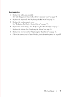
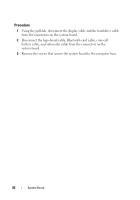
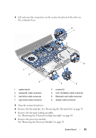
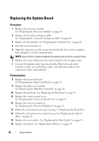
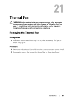
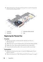
Replacing the System Board Procedure 1 Replace the processor module. See "Replacing the Processor Module" on page 95. 2 Replace the thermal cooling assembly. See "Replacing the Thermal Cooling Assembly" on page 90. 3 Replace the thermal fan. See "Replacing the Thermal Fan" on page 88. 4 Turn the system board over. 5 Align the connectors on the system board with the slots on the computer base and place it on the computer base. NOTE: Ensure that no cables lie between the system board and the computer base. 6 Replace the screws that secure the system board to the computer base. 7 Connect the display cable, logo-board cable, Bluetooth-card cable, hard-drive cable, coin-cell battery cable, and subwoofer cable to the connectors on the system-board. Postrequisites 8 Replace the mini-card board. See "Replacing the Mini-Card Board" on page 78. 9 Replace the palm-rest assembly. See "Replacing the Palm-Rest Assembly" on page 44. 10 Replace the keyboard. See "Replacing the Keyboard" on page 39. 11 Replace the center-control cover. See "Replacing the Center-Control Cover" on page 35. 12 Replace the memory module(s). See "Replacing the Memory Module(s)" on page 31. 13 Follow the instructions from step 3 to step 5 in Replacing the Hard Drive. 14 Follow the instructions from step 6 to step 8 in "Replacing the Optical Drive" on page 22. 15 Replace the mini-card(s). See "Replacing the Mini-Card(s)" on page 47. 16 Replace the battery. See "Replacing the Battery" on page 18. 84 System Board
-
 1
1 -
2
-
3
-
4
-
5
-
6
-
7
-
8
-
9
-
10
-
11
-
12
-
13
-
14
-
15
-
16
-
17
-
18
-
19
-
20
-
21
-
22
-
23
-
24
-
25
-
26
-
27
-
28
-
29
-
30
-
31
-
32
-
33
-
34
-
35
-
36
-
37
-
38
-
39
-
40
-
41
-
42
-
43
-
44
-
45
-
46
-
47
-
48
-
49
-
50
-
51
-
52
-
53
-
54
-
55
-
56
-
57
-
58
-
59
-
60
-
61
-
62
-
63
-
64
-
65
-
66
-
67
-
68
-
69
-
70
-
71
-
72
-
73
-
74
-
75
-
76
-
 77
77 -
 78
78 -
 79
79 -
 80
80 -
 81
81 -
 82
82 -
 83
83 -
 84
84 -
 85
85 -
 86
86 -
 87
87 -
88
-
89
-
90
-
91
-
92
-
93
-
94
-
95
-
96
-
97
-
98
-
99
-
100
-
101
-
102
-
103
-
104
 |
 |