| Section |
Page |
| Contents |
3 |
| Before You Begin |
9 |
| Turn Off Your Computer and Connected Devices |
9 |
| Safety Instructions |
10 |
| Recommended Tools |
10 |
| After Working Inside Your Computer |
11 |
| Base Cover |
13 |
| Removing the Base Cover |
13 |
| Procedure |
13 |
| 1 Turn the computer over. |
13 |
| 2 Loosen the captive screws that secure the base cover to the computer base. |
13 |
| 3 Slide and lift the base cover off the computer base. |
13 |
| Replacing the Base Cover |
14 |
| Procedure |
14 |
| 1 Align the tabs on the base cover with the slots on the computer base and slide the base cover until it snaps into place. |
14 |
| 2 Tighten the captive screws that secure the base cover to the computer base. |
14 |
| Postrequisites |
14 |
| 1 Follow the instructions in \ |
14 |
| 4 |
15 |
| Battery |
15 |
| Removing the Battery |
15 |
| Prerequisites |
15 |
| 1 Remove the base cover. See \ |
15 |
| Procedure |
15 |
| 1 Disconnect the battery cable from the connector on the system board. |
15 |
| 2 Loosen the captive screws that secure the battery to the computer base. |
15 |
| 3 Using the pull-tab, lift the battery off the computer base. |
16 |
| Replacing the Battery |
16 |
| Procedure |
16 |
| 1 Place the battery in the battery bay and tighten the captive screws that secure the battery to the computer base. |
16 |
| 2 Connect the battery cable to the connector on the system board. |
16 |
| Postrequisites |
16 |
| 1 Replace the base cover. See \ |
16 |
| 2 Follow the instructions in \ |
16 |
| Optical Drive |
17 |
| Removing the Optical Drive |
17 |
| Prerequisites |
17 |
| Procedure |
17 |
| Replacing the Optical Drive |
20 |
| Procedure |
20 |
| Postrequisites |
21 |
| 6 |
23 |
| Hard Drive |
23 |
| Removing the Hard Drive |
23 |
| Procedure |
23 |
| 1 Remove the base cover. See \ |
23 |
| 2 Remove the battery pack. See \ |
23 |
| 3 Follow the instructions from step 1 to step 3 in \ |
23 |
| Procedure |
23 |
| 1 Loosen the three captive screws that secure the hard-drive assembly to the computer base. |
23 |
| 2 Using the pull-tab, gently lift the hard-drive assembly and then disconnect the hard-drive interposer. |
23 |
| 3 Lift the hard-drive assembly off the computer base. |
24 |
| 4 Remove the four screws that secure the hard-drive bracket to the hard drive. |
25 |
| 5 Lift the hard-drive bracket off the hard drive. |
25 |
| Replacing the Hard Drive |
25 |
| Procedure |
25 |
| 1 Place the hard drive in the hard-drive bracket. |
25 |
| 2 Replace the four screws that secure the hard-drive bracket to the hard drive. |
25 |
| 3 Connect the interposer to the hard drive. |
25 |
| 4 Place the hard-drive assembly in the computer base. |
25 |
| 5 Tighten the three captive screws that secure the hard-drive assembly to the computer base. |
25 |
| Postrequisites |
26 |
| 1 Follow the instructions from step 6 to step 8 in \ |
26 |
| 2 Replace the battery. See \ |
26 |
| 3 Replace the base cover. See \ |
26 |
| 4 Follow the instructions in \ |
26 |
| 7 |
27 |
| Memory Module(s) |
27 |
| Removing the Memory Module(s) |
27 |
| Prerequisites |
27 |
| 1 Remove the base cover. See \ |
27 |
| 2 Remove the battery. See \ |
27 |
| Procedure |
28 |
| 1 Loosen the captive screws that secure the memory-module cover to the computer base. |
28 |
| 2 Lift and slide the tabs on the memory-module cover out of the slots on the computer base. |
28 |
| 3 Use your fingertips to carefully spread apart the securing clips on each end of the memory-module connector until the memory module pops up. |
28 |
| 4 Slide the memory module out of the memory-module connector. |
29 |
| Replacing the Memory Module(s) |
29 |
| Procedure |
29 |
| 1 Align the notch in the memory module with the tab in the memory- module connector. |
29 |
| 2 Slide the memory module firmly into the connector at a 45-degree angle, and then press the memory module down until it clicks into place. If you do not hear the click, remove the memory module and reinstall it. |
30 |
| 3 Slide the tabs on the memory-module cover into the slots on the computer base and lower the memory-module cover into place. |
30 |
| 4 Tighten the captive screws that secure the memory-module cover to the computer base. |
30 |
| Postrequisites |
30 |
| 1 Replace the battery. See \ |
30 |
| 2 Replace the base cover. See \ |
30 |
| 3 Follow the instructions in \ |
30 |
| 8 |
31 |
| Center-Control Cover |
31 |
| Removing the Center-Control Cover |
31 |
| Prerequisites |
31 |
| 1 Remove the base cover. See \ |
31 |
| 2 Remove the battery. See \ |
31 |
| Procedure |
32 |
| 1 Remove the screws that secure the center-control cover to the computer base. |
32 |
| 2 Turn the computer over and open the display as far as possible. |
32 |
| 3 Gently pry the center-control cover and then ease the tabs on the center-control cover out of the slots on the palm-rest assembly. |
32 |
| 4 Lift the center-control cover off the palm-rest assembly. |
33 |
| Replacing the Center-Control Cover |
33 |
| Procedure |
33 |
| 1 Align the tabs on the center-control cover with the slots on the palm-rest assembly. |
33 |
| 2 Gently press around the edges of the center-control cover till it snaps in place. |
33 |
| 3 Close the display and turn the computer over. |
33 |
| 4 Replace the screws that secure the center-control cover to the computer base. |
33 |
| Postrequisites |
34 |
| 1 Replace the battery pack. See \ |
34 |
| 2 Replace the base cover. See \ |
34 |
| 3 Follow the instructions in \ |
34 |
| 9 |
35 |
| Keyboard |
35 |
| Removing the Keyboard |
35 |
| Prerequisites |
35 |
| 1 Remove the base cover. See \ |
35 |
| 2 Remove the battery. See \ |
35 |
| 3 Remove the center-control cover. See \ |
35 |
| Procedure |
35 |
| 1 Remove the screws that secure the keyboard to the computer base. |
35 |
| 2 Carefully pry the keyboard up and slide it towards the display till the tabs on the keyboard are released from the palm-rest assembly. |
36 |
| 3 Turn the keyboard over. |
36 |
| 4 Lift the release latches on the connectors on the system board and disconnect the keyboard cable and keyboard-backlight cable. |
37 |
| 5 Lift the keyboard off the palm-rest assembly. |
37 |
| Replacing the Keyboard |
37 |
| Procedure |
37 |
| 1 Slide the keyboard cable and keyboard backlight cable into the connectors on the system board and press down on the connector latches to secure the cables. |
37 |
| 2 Slide the tabs on the keyboard into the slots on the palm-rest assembly and lower the keyboard into place. |
37 |
| 3 Gently press around the edges of the keyboard to secure the keyboard under the tab on the palm-rest assembly. |
37 |
| 4 Replace the screws that secure the keyboard to the computer base. |
37 |
| Postrequisites |
38 |
| 1 Replace the center-control cover. See \ |
38 |
| 2 Replace the battery. See \ |
38 |
| 3 Replace the base cover. See \ |
38 |
| 4 Follow the instructions in \ |
38 |
| 10 |
39 |
| Palm-Rest Assembly |
39 |
| Removing the Palm-Rest Assembly |
39 |
| Prerequisites |
39 |
| 1 Remove the base cover. See \ |
39 |
| 2 Remove the battery. See \ |
39 |
| Procedure |
40 |
| 1 Remove the screws that secure the palm-rest assembly to the computer base. |
40 |
| 2 Turn the computer over and open the display as far as possible. |
40 |
| 3 Remove the center-control cover (see \ |
40 |
| 4 Remove the keyboard (see \ |
40 |
| 5 Lift the connector latches and use the pull-tabs to disconnect the touchpad cable and power-button board cable from the connectors on the system board. |
40 |
| 6 Disconnect the speakers cable and status-light board cable from the connectors on the system board. |
40 |
| 7 Remove the two screws that secure the palm-rest assembly to the computer base. |
41 |
| 8 Pry out the palm-rest assembly along the rear edge and then ease the palm-rest assembly from the computer base. |
41 |
| 9 Lift the palm-rest assembly off the computer base. |
41 |
| Replacing the Palm-Rest Assembly |
42 |
| Procedure |
42 |
| 1 Align the palm-rest assembly on the computer base and gently snap the palm-rest assembly into place. |
42 |
| 2 Replace the two screws that secure the palm-rest assembly to the computer base. |
42 |
| 3 Connect the speakers cable and status-light board cable to the connectors on the system board. |
42 |
| 4 Slide the touch-pad cable and power-button board cable into their connectors on the system board, and press down on their connector latches to secure the cables. |
42 |
| Postrequisites |
42 |
| 1 Replace the keyboard. See \ |
42 |
| 2 Replace the center-control cover. See \ |
42 |
| 3 Close the display and turn the computer over. |
42 |
| 4 Replace the screws that secure the palm-rest assembly to the computer base. |
42 |
| 5 Replace the battery. See \ |
42 |
| 6 Replace the base cover. See \ |
42 |
| 7 Follow the instructions in \ |
42 |
| 11 |
43 |
| Wireless Mini-Card(s)/WirelessHD Card (Optional) |
43 |
| Removing the Mini-Card(s) |
43 |
| Prerequisites |
43 |
| 1 Remove the base cover. See \ |
43 |
| 2 Remove the battery. See \ |
43 |
| Procedure |
44 |
| 1 Disconnect the antenna cables from the connectors on the mini-card. |
44 |
| 2 Remove the screw that secures the mini-card to the system board. |
44 |
| 3 Slide and remove the mini-card out of the connector on the system board. |
45 |
| Replacing the Mini-Card(s) |
45 |
| Procedure |
45 |
| 1 Remove the new Mini-Card from its packaging. |
45 |
| 2 Insert the mini-card connector at a 45-degree angle into the connector on the system board. |
45 |
| 3 Press the other end of the mini-card down into the slot on the system board and replace the screw that secures the mini-card to the system board. |
45 |
| 4 Connect the mini-card cables to the connectors on the mini-card. The following table provides the antenna cable color scheme for each mini-card supported by your computer: |
46 |
| Postrequisites |
46 |
| 1 Replace the battery. See \ |
46 |
| 2 Replace the base cover. See \ |
46 |
| 3 Follow the instructions in \ |
46 |
| 12 |
47 |
| Power-Button Board |
47 |
| Removing the Power-Button Board |
47 |
| Prerequisites |
47 |
| 1 Remove the base cover. See \ |
47 |
| 2 Remove the battery. See \ |
47 |
| 3 Remove the center-control cover. See \ |
47 |
| 4 Remove the keyboard. See \ |
47 |
| 5 Remove the palm-rest assembly. See \ |
47 |
| Procedure |
47 |
| 1 Gently peel the power-button board cable from the palm-rest assembly. |
47 |
| 2 Remove the screws that secure the power-button board to the palm-rest assembly. |
47 |
| 3 Carefully lift the power-button board and release its cable from the slot on the palm-rest assembly. |
48 |
| Replacing the Power-Button Board |
48 |
| Procedure |
48 |
| 1 Slide the power-button board cable through the slot on the palm-rest assembly. |
48 |
| 2 Use the alignment posts on the palm-rest assembly to place the power-button board in place. |
48 |
| 3 Replace the screws that secure the power-button board to the palm-rest assembly. |
48 |
| 4 Adhere the power-button board cable to the palm-rest assembly. |
48 |
| Postrequisites |
49 |
| 1 Replace the palm-rest assembly. See \ |
49 |
| 2 Replace the keyboard. See \ |
49 |
| 3 Replace the center-control cover. See \ |
49 |
| 4 Replace the battery pack. See \ |
49 |
| 5 Replace the base cover. See \ |
49 |
| 6 Follow the instructions in \ |
49 |
| 13 |
51 |
| Status-Lights Board |
51 |
| Removing the Status-Lights Board |
51 |
| Prerequisites |
51 |
| 1 Remove the base cover. See \ |
51 |
| 2 Remove the battery. See \ |
51 |
| 3 Remove the center-control cover. See \ |
51 |
| 4 Remove the keyboard. See \ |
51 |
| 5 Remove the palm-rest assembly. See \ |
51 |
| Procedure |
51 |
| 1 Turn the palm-rest assembly over. |
51 |
| 2 Note the routing of status-light board cable and remove the cable from the routing guides. |
51 |
| 3 Turn the palm-rest assembly over. |
52 |
| 4 Remove the screw that secures the status-light board to the palm- rest assembly. |
53 |
| 5 Carefully lift the status-light board and release its cable from the slot on the palm-rest assembly. |
53 |
| Replacing the Status-Lights Board |
53 |
| Procedure. |
53 |
| 1 Slide the status-light board cable through the slot in the palm-rest assembly. |
53 |
| 2 Align the slot on the status-light board with the alignment post on the palm-rest assembly. |
53 |
| 3 Replace the screw that secures the status-light board to the palm-rest assembly. |
53 |
| 4 Turn the palm-rest assembly over. |
53 |
| 5 Route the status-light board cable through the routing guides on the palm-rest assembly. |
53 |
| Postrequisites |
54 |
| 6 Replace the palm-rest assembly. See \ |
54 |
| 7 Replace the keyboard. See \ |
54 |
| 8 Replace the center-control cover. See \ |
54 |
| 9 Replace the battery. See \ |
54 |
| 10 Replace the base cover. See \ |
54 |
| 11 Follow the instructions in \ |
54 |
| 14 |
55 |
| Speakers |
55 |
| Removing the Speakers |
55 |
| Prerequisites |
55 |
| 1 Remove the base cover. See \ |
55 |
| 2 Remove the battery. See \ |
55 |
| 3 Remove the center-control cover. See \ |
55 |
| 4 Remove the keyboard. See \ |
55 |
| 5 Remove the palm-rest assembly. See \ |
55 |
| Procedure |
55 |
| 1 Turn the palm-rest assembly over. |
55 |
| 2 Note the routing of speakers cable and remove the cable from the routing guides. |
55 |
| 3 Remove the four screws that secure the speakers to the palm-rest assembly. |
56 |
| 4 Lift the speakers along with the cable away from the palm-rest assembly. |
56 |
| Replacing the Speakers |
56 |
| Procedure |
56 |
| 1 Align the screw holes on the speakers with the screw holes on the palm-rest assembly and route the speakers cable through the routing guides. |
56 |
| 2 Replace the screws that secure the speakers to the palm-rest assembly. |
56 |
| 3 Turn the palm-rest assembly over. |
56 |
| Postrequisites |
57 |
| 1 Replace the palm-rest assembly. See \ |
57 |
| 2 Replace the keyboard. See \ |
57 |
| 3 Replace the center-control cover. See \ |
57 |
| 4 Replace the battery. See \ |
57 |
| 5 Replace the base cover. See \ |
57 |
| 6 Follow the instructions in \ |
57 |
| 15 |
59 |
| Subwoofer |
59 |
| Removing the Subwoofer |
59 |
| Prerequisites |
59 |
| 1 Remove the base cover. See \ |
59 |
| 2 Remove the battery. See \ |
59 |
| 3 Remove the center-control cover. See \ |
59 |
| 4 Remove the keyboard. See \ |
59 |
| 5 Remove the palm-rest assembly. See \ |
59 |
| Procedure |
59 |
| 1 Disconnect the subwoofer cable from the connector on the system board. |
59 |
| 2 Note the routing of subwoofer cable and remove the cable from the routing guides. |
59 |
| 3 Lift the subwoofer along with the cable off the computer base. |
60 |
| Replacing the Subwoofer |
60 |
| Procedure |
60 |
| 1 Align the slots on the subwoofer with the alignment posts on the computer base. |
60 |
| 2 Route the subwoofer cable through the routing guides. |
60 |
| 3 Connect the subwoofer cable to the connector on the system board. |
60 |
| Postrequisites |
60 |
| 1 Replace the palm-rest assembly. See \ |
60 |
| 2 Replace the keyboard. See \ |
60 |
| 3 Replace the center-control cover. See \ |
60 |
| 4 Replace the battery. See \ |
61 |
| 5 Replace the base cover. See \ |
61 |
| 6 Follow the instructions in \ |
61 |
| 16 |
63 |
| Internal Card with Bluetooth Wireless Technology |
63 |
| Removing the Bluetooth Card |
63 |
| Prerequisites |
63 |
| 1 Remove the base cover. See \ |
63 |
| 2 Remove the battery. See \ |
63 |
| 3 Remove the center-control cover. See \ |
63 |
| 4 Remove the keyboard. See \ |
63 |
| 5 Remove the palm-rest assembly. See \ |
63 |
| Procedure |
63 |
| 1 Disconnect the Bluetooth-card cable from the connector on the system board. |
63 |
| 2 Remove the screw that secures the Bluetooth card to the computer base. |
63 |
| 3 Note the routing of Bluetooth-card cable and remove the cable from the routing guides. |
63 |
| 4 Lift the Bluetooth card along with the cable off the computer base. |
63 |
| Replacing the Bluetooth Card |
64 |
| Procedure |
64 |
| 1 Align the screw hole on the Bluetooth card with the screw hole on the system board. |
64 |
| 2 Replace the screw that secures the Bluetooth card to the computer base. |
64 |
| 3 Connect the Bluetooth-card cable to the connector on the system board. |
64 |
| Postrequisites |
64 |
| 1 Replace the palm-rest assembly. See \ |
64 |
| 2 Replace the keyboard. See \ |
64 |
| 3 Replace the center-control cover. See \ |
64 |
| 4 Replace the battery. See \ |
65 |
| 5 Replace the base cover. See \ |
65 |
| 6 Follow the instructions in \ |
65 |
| 17 |
67 |
| Coin-Cell Battery |
67 |
| Removing the Coin-Cell Battery |
67 |
| Prerequisites |
67 |
| 1 Remove the base cover. See \ |
67 |
| 2 Remove the battery pack. See \ |
67 |
| 3 Remove the center-control cover. See \ |
67 |
| 4 Remove the keyboard. See \ |
67 |
| 5 Remove the palm-rest assembly. See \ |
67 |
| Procedure |
68 |
| 1 Disconnect the coin-cell battery cable from the connector on the system board. |
68 |
| 2 Gently pry out the coin-cell battery from the slot on the computer base. |
68 |
| Replacing the Coin-Cell Battery |
68 |
| Procedure |
68 |
| 1 Use the adhesive on the coin-cell battery and adhere it to slot on the computer base. |
68 |
| 2 Connect the coin-cell battery cable to the connector on the system board. |
68 |
| Postrequisites |
69 |
| 1 Replace the palm-rest assembly. See \ |
69 |
| 2 Replace the keyboard. See \ |
69 |
| 3 Replace the center-control cover. See \ |
69 |
| 4 Replace the battery. See \ |
69 |
| 5 Replace the base cover. See \ |
69 |
| 6 Follow the instructions in \ |
69 |
| 18 |
71 |
| Display Assembly |
71 |
| Removing the Display Assembly |
71 |
| Prerequisites |
71 |
| 1 Remove the base cover. See \ |
71 |
| 2 Remove the battery pack. See \ |
71 |
| 3 Disconnect the antenna cables from the mini-card(s). See \ |
71 |
| 4 Note the routing of the WirelessHD card (optional) and mini-card antenna cables and remove them from the routing guides on the computer base. |
72 |
| 5 Turn the computer over and open the display as far as possible. |
72 |
| 6 Remove the center-control cover. See \ |
72 |
| 7 Remove the keyboard. See \ |
72 |
| 8 Remove the palm-rest assembly. See \ |
72 |
| Procedure |
73 |
| 1 Using the pull-tab, disconnect the display cable from the connector on the system board. |
73 |
| 2 Disconnect the logo-board cable from the connector on the system board. |
73 |
| 3 Gently peel the display cable and the logo-board cable from the system board. |
73 |
| 4 Remove the screws that secure the display assembly to the computer base. |
73 |
| 5 Gently slide the WirelessHD (optional) and mini-card antenna cables out through the slot on the computer base. |
73 |
| 6 Lift the display assembly off the computer. |
73 |
| Replacing the Display Assembly |
74 |
| Procedure |
74 |
| 1 Slide the WirelessHD (optional) and mini-card antenna cables through the slot on the computer base. |
74 |
| 2 Place the display assembly in position and replace the screws that secure the display assembly to the computer base. |
74 |
| 3 Connect the display cable and the logo-board cable to the connectors on the system board. |
74 |
| Postrequisites |
74 |
| 1 Replace the palm-rest assembly. See \ |
74 |
| 2 Replace the keyboard. See \ |
74 |
| 3 Replace the center-control cover. See \ |
74 |
| 4 Turn the computer over and route the WirelessHD card and mini-card antenna cables through the routing guides on the computer base. |
74 |
| 5 Connect the Mini-Card antenna cables to the mini-card(s). See \ |
74 |
| 6 Replace the battery. See \ |
74 |
| 7 Replace the base cover. See \ |
74 |
| 8 Follow the instructions in \ |
74 |
| 19 |
75 |
| Mini-Card Board |
75 |
| Removing the Mini-Card Board |
75 |
| Prerequisites |
75 |
| 1 Remove the base cover. See \ |
75 |
| 2 Remove the battery. See \ |
75 |
| 3 Remove the mini-card(s). See \ |
75 |
| 4 Remove the center-control cover. See \ |
75 |
| 5 Remove the keyboard. See \ |
75 |
| 6 Remove the palm-rest assembly. See \ |
75 |
| Procedure |
76 |
| 1 Remove the screws that secure the mini-card board to the computer base. |
76 |
| 2 Lift the mini-card board to disconnect the connector on the mini-card board from the connector on the system board. |
76 |
| Replacing the Mini-Card Board |
76 |
| Procedure |
76 |
| 1 Align the connector on the mini-card board with the connector on the system board and press gently. |
76 |
| 2 Replace the three screws that secure the mini-card board to the computer base. |
76 |
| Postrequisites |
77 |
| 3 Replace the palm-rest assembly. See \ |
77 |
| 4 Replace the keyboard. See \ |
77 |
| 5 Replace the center-control cover. See \ |
77 |
| 6 Replace the mini-card(s). See \ |
77 |
| 7 Replace the battery. See \ |
77 |
| 8 Replace the base cover. See \ |
77 |
| 9 Follow the instructions in \ |
77 |
| 20 |
79 |
| System Board |
79 |
| Removing the System Board |
79 |
| Prerequisites |
79 |
| 1 Remove any installed card or blank from the 9-in-1 Media Card reader. |
79 |
| 2 Remove the base cover. See \ |
79 |
| 3 Remove the battery pack. See \ |
79 |
| 4 Remove the mini-card(s). See \ |
79 |
| 5 Follow the instructions from step 1 to step 3 in \ |
79 |
| 6 Follow the instructions from step 1 to step 3 in Removing the Hard Drive. |
79 |
| 7 Remove the memory module(s). See \ |
79 |
| 8 Remove the center-control cover. See \ |
79 |
| 9 Remove the keyboard. See \ |
79 |
| 10 Remove the palm-rest assembly. See \ |
79 |
| 11 Remove the Mini-Card board. See \ |
79 |
| Procedure |
80 |
| 1 Using the pull-tab, disconnect the display cable and the hard-drive cable from the connectors on the system board. |
80 |
| 2 Disconnect the logo-board cable, Bluetooth-card cable, coin-cell battery cable, and subwoofer cable from the connectors on the system board. |
80 |
| 3 Remove the screws that secure the system board to the computer base. |
80 |
| 4 Lift and ease the connectors on the system board out of the slots on the computer base. |
81 |
| 5 Turn the system board over. |
81 |
| 6 Remove the thermal fan. See \ |
81 |
| 7 Remove the thermal cooling assembly. See \ |
81 |
| 8 Remove the processor module. See \ |
81 |
| Replacing the System Board |
82 |
| Procedure |
82 |
| 1 Replace the processor module. See \ |
82 |
| 2 Replace the thermal cooling assembly. See \ |
82 |
| 3 Replace the thermal fan. See \ |
82 |
| 4 Turn the system board over. |
82 |
| 5 Align the connectors on the system board with the slots on the computer base and place it on the computer base. |
82 |
| 6 Replace the screws that secure the system board to the computer base. |
82 |
| 7 Connect the display cable, logo-board cable, Bluetooth-card cable, hard-drive cable, coin-cell battery cable, and subwoofer cable to the connectors on the system-board. |
82 |
| Postrequisites |
82 |
| 8 Replace the mini-card board. See \ |
82 |
| 9 Replace the palm-rest assembly. See \ |
82 |
| 10 Replace the keyboard. See \ |
82 |
| 11 Replace the center-control cover. See \ |
82 |
| 12 Replace the memory module(s). See \ |
82 |
| 13 Follow the instructions from step 3 to step 5 in Replacing the Hard Drive. |
82 |
| 14 Follow the instructions from step 6 to step 8 in \ |
82 |
| 15 Replace the mini-card(s). See \ |
82 |
| 16 Replace the battery. See \ |
82 |
| 17 Replace the base cover. See \ |
83 |
| 18 Replace any cards or blank that you removed from the 9-in-1 Media Card reader. |
83 |
| 19 Follow the instructions in \ |
83 |
| Entering the Service Tag in the BIOS |
83 |
| 1 Ensure that the AC adapter is plugged in and that the main battery is installed properly. |
83 |
| 2 Turn on the computer. |
83 |
| 3 Press <F2> during POST to enter the system setup program. |
83 |
| 4 Navigate to the Security tab and enter the service tag in the Set Service Tag field. |
83 |
| 21 |
85 |
| Thermal Fan |
85 |
| Removing the Thermal Fan |
85 |
| Prerequisites |
85 |
| 1 Follow the instructions from step 1 to step 4 in \ |
85 |
| Procedure |
85 |
| 1 Disconnect the thermal-fan cable from the connector on the system board. |
85 |
| 2 Remove the screws that secure the thermal fan to the system board. |
85 |
| 3 Lift the thermal fan and gently peel the tape that secures the thermal fan to the thermal cooling assembly. |
86 |
| Replacing the Thermal Fan |
86 |
| Procedure |
86 |
| 1 Align the screw holes on the thermal fan with the screw holes on the system board. |
86 |
| 2 Adhere the tape to secure the thermal fan to the thermal cooling assembly. |
86 |
| 3 Replace the screws that secure the thermal fan to the system board. |
86 |
| 4 Connect the thermal-fan cable to the connector on the system board. |
86 |
| Postrequisites |
86 |
| 1 Follow the instructions from step 2 to step 18 in \ |
86 |
| 2 Follow the instructions in \ |
86 |
| 22 |
87 |
| Thermal Cooling Assembly |
87 |
| Removing the Thermal Cooling Assembly |
87 |
| Prerequisites |
87 |
| 1 Follow the instructions from step 1 to step 6 in \ |
87 |
| Procedure |
87 |
| 1 In sequential order (indicated on the thermal cooling assembly), loosen the captive screws that secure the thermal cooling assembly to the system board. |
87 |
| 2 Carefully lift thermal cooling assembly away from the system board. |
88 |
| Replacing the Thermal Cooling Assembly |
88 |
| Procedure |
88 |
| 1 Clean the thermal grease from the bottom of the thermal cooling assembly and reapply it. |
88 |
| 2 Align the captive screws on the thermal cooling assembly with the screw holes on the system board and tighten the screws in sequential order (indicated on the thermal cooling assembly). |
88 |
| Postrequisites |
89 |
| 1 Follow the instructions from step 3 to step 18 in \ |
89 |
| 2 Follow the instructions in \ |
89 |
| 23 |
91 |
| Processor Module |
91 |
| Removing the Processor Module |
91 |
| Prerequisites |
91 |
| 1 Follow the instructions from step 1 to step 7 in \ |
91 |
| Procedure |
91 |
| 1 To loosen the ZIF socket, use a small, flat-blade screwdriver and rotate the ZIF-socket cam screw counterclockwise until it comes to the cam stop. |
91 |
| 2 Lift the processor module off the ZIF socket. |
92 |
| Replacing the Processor Module |
93 |
| Procedure |
93 |
| 1 Align the pin-1 corner of the processor module with the pin-1 corner of the ZIF socket. |
93 |
| 2 Place the processor module lightly in the ZIF socket and ensure that the processor module is positioned correctly. |
93 |
| 3 Tighten the ZIF socket by turning the cam screw clockwise to secure the processor module to the system board. |
93 |
| Postrequisites |
93 |
| 1 Follow the instructions from step 2 to step 18 in \ |
93 |
| 2 Follow the instructions in \ |
93 |
| 24 |
95 |
| System Setup |
95 |
| Overview |
95 |
| Entering System Setup |
95 |
| 1 Turn on (or restart) your computer. |
95 |
| 2 During POST, when the DELL logo is displayed, watch for the F2 prompt to appear and then press <F2> immediately. |
95 |
| System Setup Screens |
95 |
| Boot Sequence |
101 |
| Boot Options |
101 |
| Changing Boot Sequence for the Current Boot |
101 |
| 1 If you are booting from a USB device, connect the USB device to a USB connector. |
101 |
| 2 Turn on (or restart) your computer. |
101 |
| 3 When F2 Setup, F12 Boot Options appears in the lower-right corner of the screen, press <F12>. |
101 |
| 4 On the Boot Device Menu choose the device you want to boot from and press <Enter>. |
101 |
| Changing Boot Sequence for Future Boots |
102 |
| 1 Enter system setup. See \ |
102 |
| 2 Use the arrow keys to highlight the Boot menu option and press <Enter> to access the menu. |
102 |
| 3 Press the up- and down-arrow keys to move through the list of devices. |
102 |
| 4 Press plus (F5) or minus (F6) to change the boot priority of the device. |
102 |

 1
1 76
76 77
77 78
78 79
79 80
80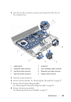 81
81 82
82 83
83 84
84 85
85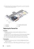 86
86

