Dell Alienware M17X R2 Service Manual - Page 47
Removing the Brackets, Replacing the Brackets
 |
View all Dell Alienware M17X R2 manuals
Add to My Manuals
Save this manual to your list of manuals |
Page 47 highlights
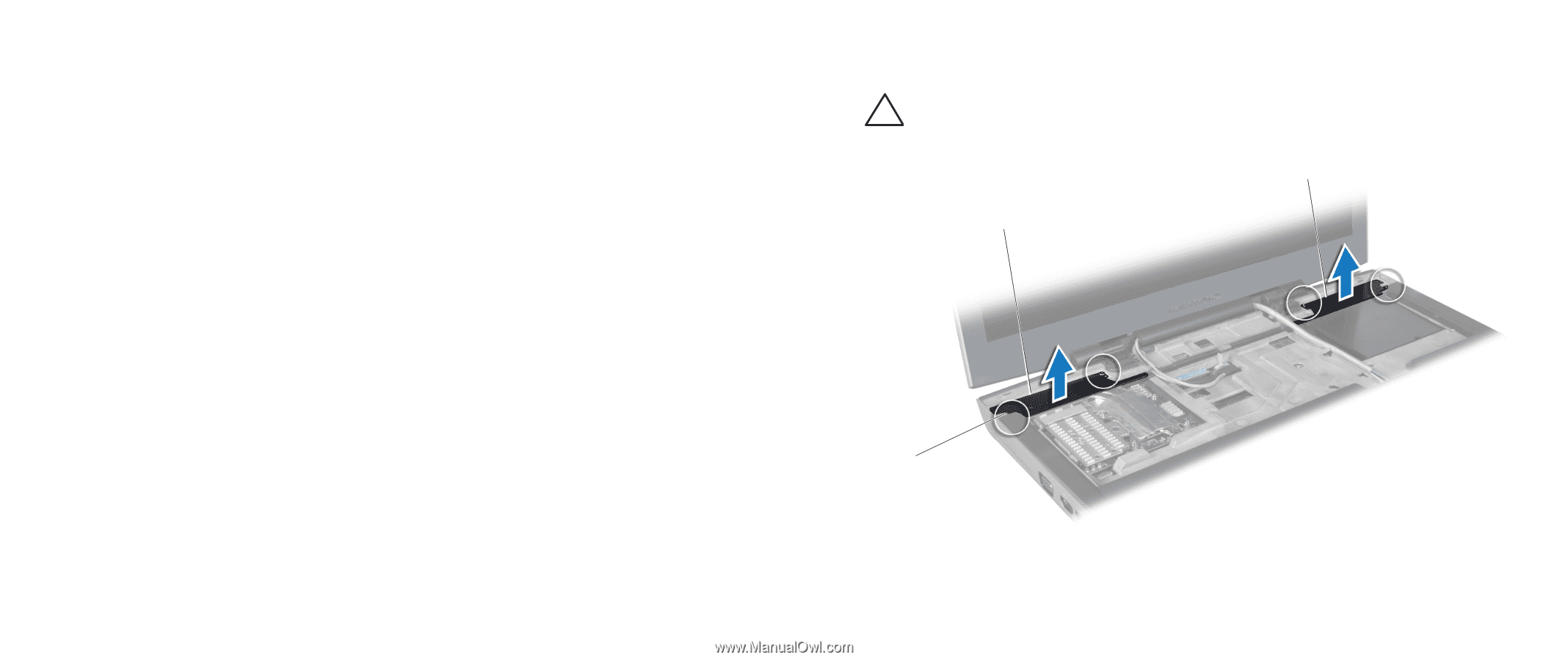
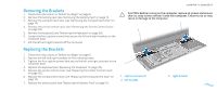
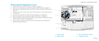
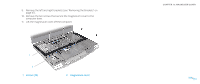
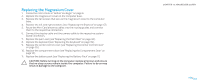
Removing the Brackets 1. Follow the instructions in "Before You Begin" on page 6. 2. Remove the battery pack (see "Removing the Battery Pack" on page 11). 3. Remove the compartment door (see "Removing the Compartment Door" on page 14). 4. Remove the center control cover (see "Removing the Center Control Cover" on page 33). 5. Remove the keyboard (see "Removing the Keyboard" on page 38). 6. Loosen the four captive screws that secure the left and right brackets to the computer base. 7. Lift the left and right brackets off the computer. CHAPTER 11: BRACKETS CAUTION: Before turning on the computer, replace all screws and ensure that no stray screws remain inside the computer. Failure to do so may result in damage to the computer. 3 2 Replacing the Brackets 1. Follow the instructions in "Before You Begin" on page 6. 2. Replace the left and right brackets on the computer base. 3. Tighten the four captive screws that secure the left and right brackets to the computer base. 4. Replace the keyboard (see "Replacing the Keyboard" on page 39). 5. Replace the center control cover (see "Replacing the Center Control Cover" on page 35). 6. Replace the compartment door (see "Replacing the Compartment Door" on page 14). 7. Replace the battery pack (see "Replacing the Battery Pack" on page 11). 1 1 captive screws (4) 2 left bracket 3 right bracket 047 /047
-
 1
1 -
2
-
3
-
4
-
5
-
6
-
7
-
8
-
9
-
10
-
11
-
12
-
13
-
14
-
15
-
16
-
17
-
18
-
19
-
20
-
21
-
22
-
23
-
24
-
25
-
26
-
27
-
28
-
29
-
30
-
31
-
32
-
33
-
34
-
35
-
36
-
37
-
38
-
39
-
40
-
41
-
 42
42 -
 43
43 -
 44
44 -
 45
45 -
 46
46 -
 47
47 -
 48
48 -
 49
49 -
 50
50 -
 51
51 -
 52
52 -
53
-
54
-
55
-
56
-
57
-
58
-
59
-
60
-
61
-
62
-
63
-
64
-
65
-
66
-
67
-
68
-
69
-
70
-
71
-
72
-
73
-
74
-
75
-
76
-
77
-
78
-
79
-
80
-
81
-
82
-
83
-
84
-
85
-
86
-
87
-
88
-
89
-
90
-
91
-
92
-
93
-
94
-
95
-
96
-
97
-
98
-
99
-
100
-
101
-
102
-
103
-
104
-
105
-
106
-
107
-
108
-
109
-
110
-
111
-
112
-
113
-
114
-
115
-
116
-
117
-
118
 |
 |