Dell Alienware M17X R2 Service Manual - Page 71
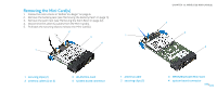
Replacing the Optical Drive
 |
View all Dell Alienware M17X R2 manuals
Add to My Manuals
Save this manual to your list of manuals |
Page 71 highlights
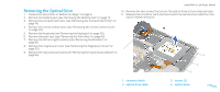
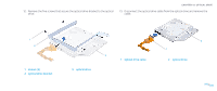
Replacing the Optical Drive 1. Follow the instructions in "Before You Begin" on page 6. 2. Connect the optical drive cable to the optical drive. 3. Replace the five screws that secure the optical drive bracket to the optical drive. 4. Place the optical drive in the computer base. 5. Slide the optical drive cable into the system board connector and pull down the connector latch to secure the cable to the connector. 6. Replace the two screws that secure the optical drive to the computer base. 7. Replace the input/output board (see "Replacing the Input/Output Board" on page 66). 8. Replace the magnesium cover (see "Replacing the Magnesium Cover" on page 52). 9. Replace the left and right brackets (see "Replacing the Brackets" on page 47). 10. Replace the palm rest (see "Replacing the Palm Rest" on page 44). 11. Replace the keyboard (see "Replacing the Keyboard" on page 39). 12. Replace the center control cover (see "Replacing the Center Control Cover" on page 35). 13. Replace the compartment door (see "Replacing the Compartment Door" on page 14). 14. Replace the battery pack (see "Replacing the Battery Pack" on page 11). CAUTION: Before turning on the computer, replace all screws and ensure that no stray screws remain inside the computer. Failure to do so may result in damage to the computer. CHAPTER 15: OPTICAL DRIVE 071 /071
-
 1
1 -
2
-
3
-
4
-
5
-
6
-
7
-
8
-
9
-
10
-
11
-
12
-
13
-
14
-
15
-
16
-
17
-
18
-
19
-
20
-
21
-
22
-
23
-
24
-
25
-
26
-
27
-
28
-
29
-
30
-
31
-
32
-
33
-
34
-
35
-
36
-
37
-
38
-
39
-
40
-
41
-
42
-
43
-
44
-
45
-
46
-
47
-
48
-
49
-
50
-
51
-
52
-
53
-
54
-
55
-
56
-
57
-
58
-
59
-
60
-
61
-
62
-
63
-
64
-
65
-
 66
66 -
 67
67 -
 68
68 -
 69
69 -
 70
70 -
 71
71 -
 72
72 -
 73
73 -
 74
74 -
 75
75 -
 76
76 -
77
-
78
-
79
-
80
-
81
-
82
-
83
-
84
-
85
-
86
-
87
-
88
-
89
-
90
-
91
-
92
-
93
-
94
-
95
-
96
-
97
-
98
-
99
-
100
-
101
-
102
-
103
-
104
-
105
-
106
-
107
-
108
-
109
-
110
-
111
-
112
-
113
-
114
-
115
-
116
-
117
-
118
 |
 |